
In this lesson, simulate the injection molding of a part made from two different materials with in the same mold using the Plastic Injection App on the 3DEXPERIENCE platform.
Open the part in SOLIDWORKS. Save the part in your Collaborative space using an existing Bookmark. Return to your SOLIDWORKS desktop. Lock the part. Apply the Plastic Injection App. Create the FE Model or FEM.
Assign the appropriate domains to the geometries that contribute to the molding simulation. Note: A domain must be assigned to all geometries that contribute to the simulation.
Specify the filling sequence (order in which to fill the cavities).
Apply Generic ABS material to the Body. Apply DuPont™ Engineering Polymers / HYTREL ® 5526 material to the Grip. The materials you select must have the Injection molding behavior specified in their simulation domains.
Define the Fill, Pack, and Warp process settings for the two-shot plastic injection molding simulation.
Define the process settings. Modify the injection fill rate and pack switch point.
Define the injection point on Body and Grip. Define the mesh capture order to facilitate the creation of the conformal mesh between the Body and Grip.
Refine the mesh element size. Mesh the model.
Run the Simulation study. Use the Physics Results Explorer App. Note: The Simulation should take approximately 6 – 7 minutes using 4 CPU cores.
View the created simulations: Fill, Pack + Cool and Warp. Analyze various simulation contour plots.
Create an animation of the Warp Simulation – Total Displacement contour plot. Save the study. Close the study.
Before we start, there are a few items that you need to know.
In this lesson, use your default Collaborative space. An internet connection is required. A 3DEXPERIENCE ID is required.
The Simulation lesson provides a foundation to users who are new to using simulation to solve real-world engineering and design problems. Before you use the Plastic Injection App, you must define all required parts. For example, you must have a model of the part cavity defined as a single solid part. If you plan to simulate the temperature distribution in the mold, you must also define any mold cooling lines as solid parts. You can use the Functional Plastic or Mold Tooling Design Apps to create these parts.
Launch 3DEXPERIENCE Platform and SOLIDWORKS
3DEXPERIENCE Launcher needs to be installed. 3DEXPERIENCE Works Lesson 1: Getting Started with SOLIDWORKS.
The 3DEXPERIENCE platform is browser driven. Your existing cookies and cache determine what you will see on your computer desktop or during a SOLIDWORKS login. A full installation of SOLIDWORKS 2019 SP0 or later is required.
Start a SOLIDWORKS session from your desktop.
Double-click the SOLIDWORKS icon.
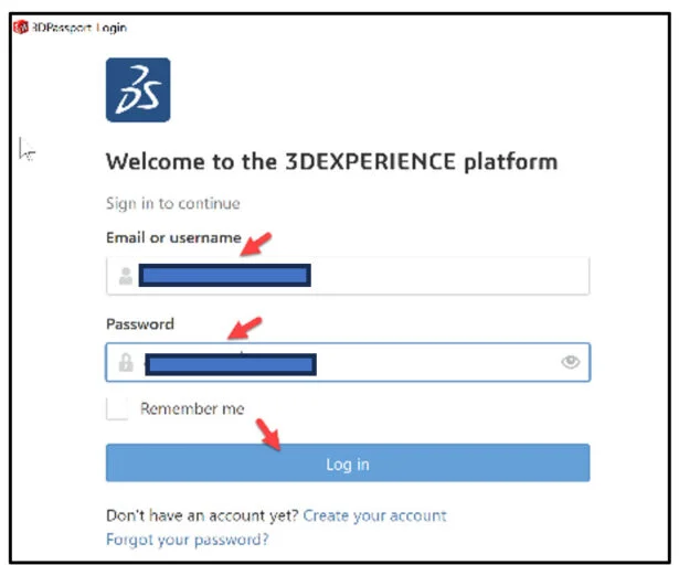
View the illustration below. Depending on your system setup, cookies, and cache, it will be different. Read the provided information.
Input the requested data.
Click Accept All.
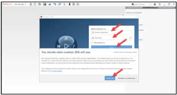
The Welcome – SOLIDWORKS dialog box is displayed.
You are logged into the 3DEXPERIENCE platform.
Close the Welcome dialog box.
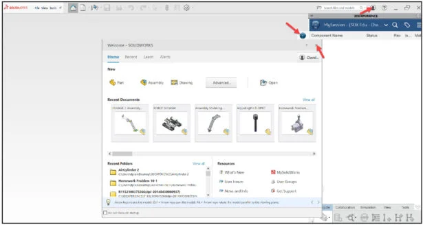
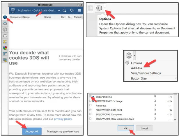
Click the 3DEXPERIENCE icon in the Task Pane. The MySession panel is displayed. This displays the two-way communication between SOLIDWORKS running on your desktop and the 3DEXPERIENCE platform running in the cloud.
In this lesson, I’m using a Collaborative space named Quick Start xDesign.
Note: If you do not see the 3DEXPERIENCE icon, click the Options drop-down arrow, click Add-Ins, check the 3DEXPERIENCE box, click OK, from the SOLIDWORKS Main menu.
Click Accept All if needed.
Download Brush Handle and Save to Platform
Open the Brush Handle part that has not been previously uploaded or saved to the 3DEXPERIENCE platform. Do not run Feature recognition. View the two Injection points (Body and Grip).
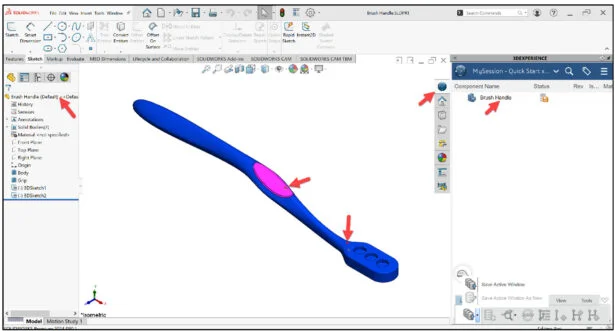
Expand the Task Pane bar. The MySession panel displays the Components Name, Status (Displays an icon that represents the status of a given revision, save or not saved to the platform), Locked status (Locked or Unlocked), Rev (Revision #), Is Last Revision (Yes/No), Maturity State (Lifecycle state of the family, for example: Private, In Work, Frozen, Released, Obsolete), Description, File Name (Displays the PLM external ID of the object for reference objects and the PLM external ID of the connection for instances) and Type (Physical Product or Drawing).
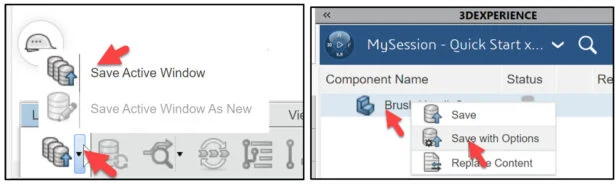
The orange save Status icon for the Brush Handle part informs you that the local file on your computer have not been saved to the platform. Save the part to the 3DEXPERIENCE platform.
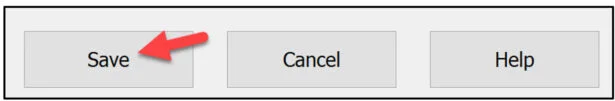
Click Save Active Window from the Lifecycle tab in the Action bar. Note: You can also right-click Race Car Body in MySession, and click Save with Options.
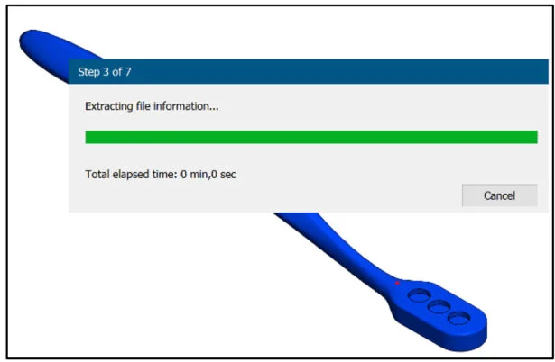
The file is temporarily being saved to a local cache area. The platform is checking for out-of-date components, modified components from the last save to the platform, different revisions, missing components, etc.
The Save to 3DEXPERIENCE dialog box is displayed. Product lifecycle management (PLM) attributes are displayed. The PLM attributes include: Bookmark locations, Selected Collaborative space, Owner, Title, Saved Status (3DEXPERIENCE), Revision, Maturity Lifecycle State and Collaborative Space name.
Save the part. Use your existing Collaborative space. Use an existing Bookmark. Note: If needed review 3DEXPERIENCE Works Lesson 3: SOLIDWORKS Bookmarks, Share and Delete. Use Bookmarks (links) to delete entire groups of data or just a single file. For assemblies within the Bookmark folder, there is an option to delete the entire structure of the assembly and all reference components.
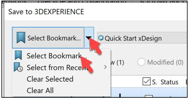
Click the Select Bookmark down arrow.
Click Select Bookmark. The Select a Bookmark dialog box is displayed.
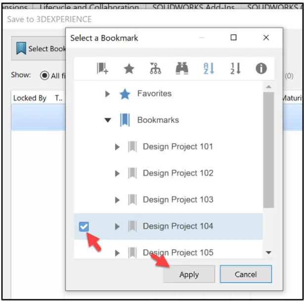
In the below example, I selected Design Project 104 as my bookmark.
Click Apply from the Select a Bookmark dialog box.
Click Save from the Save to 3DEXPERIENCE dialog box.
The part is directly loaded into your Collaborative space and Bookmarked on the 3DEXPERIENCE platform. You are returned back into your SOLIDWORKS desktop session.
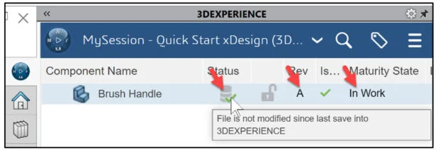
View the Status column in the updated MySession panel. The Status icon displays a green check mark. This means that the current file on your SOLIDWORKS desktop is updated and saved to the platform. The default Revision is A. The Maturity State is “In Work”. This is the default Lifecycle state after you saved the model to the 3DEXPERIENCE platform.
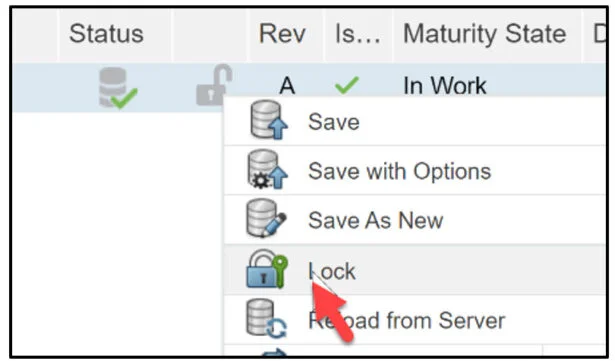
Lock the part in the MySession panel. This prevents anyone in making a change to the part.
Right-click the part name.
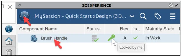
Click Lock. The part is locked.
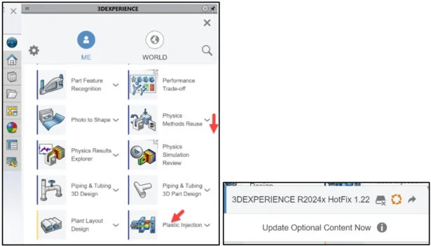
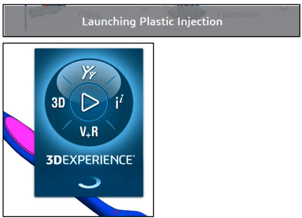
Launch Plastic Injection App
Select the Brush Handle part from the MySession panel.
Click the center of the Compass. Use the Plastic Injection App. Think of this App as the SOLIDWORKS Flow Simulation Add-in inside of SOLIDWORKS. Most of the 3DEXPERIENCE Apps run in your web browser. 3DEXPERIENCE Simulation Apps perform a small installation on your windows machine. Both types of Apps are linked to your PLM data on the platform.
Drag the slider downward to view the Plastic Injection App.
Launch the Plastic Injection App. If this is your first time using a 3DEXPERIENCE Simulation App, or an update is available, download the needed App information on your computer. It is recommend to restart your SOLIDWORKS session.
This can take 10 – 15 seconds.
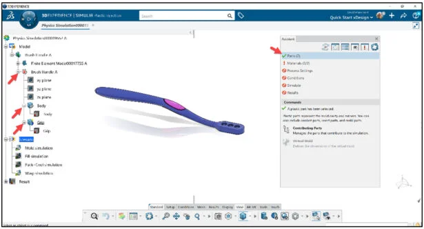
The 3DEXPERIENCE | SIMULIA Plastic Injection Creation App is displayed.
Display Model, Scenario, Result
Display the Simulation tree.
Right-click in the Graphics area.
Click Display.
Click Tree Display from the drop-down menu as illustrated.
View the default Simulation tree.
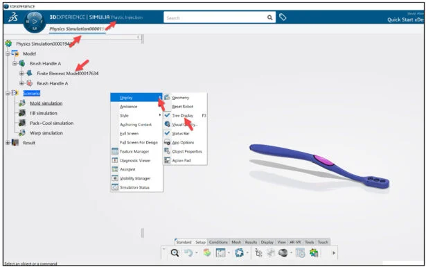
The Simulation study tree displays the simulation process: Model, Scenario, and Result.
Set mouse profile to SOLIDWORKS.
Click your profile picture (Avatar).
Click Preferences from the drop-down menu.
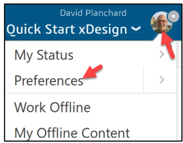
The Preference dialog box is displayed. View your options.
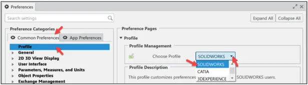
Click the Common Preferences tab.
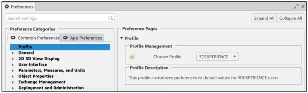
Click Profile.
Select a Profile from the Profile Management drop-down menu (SOLIDWORKS).
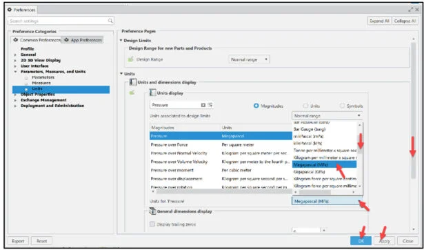
Check the solver units for Pressure and Temperature.
In this example we use Pressure – Megapascal Mpa. Temperature – Celsius C.
Expand Parameters, Measures, and Units.
Click Units.
Drag the slider downward to view Pressure.
Note: To modify the default unit, drag the inside and outside slider downward to locate the magnitude, select the magnitude, select the new unit from the drop-down menu as illustrated.
Click Apply. Perform the same process for Temperature.
Click OK from the Preferences dialog box.
Assign the appropriate domains to the geometries that contribute to the simulation.
A domain characterized the type of component (Physical Product) of an injection molding machine that is included in a simulation. A domain must be assigned to all geometries that contribute to the simulation. The domains include:
- Plastic, which represents a model cavity.
- Part (Physical Product) insert.
- Hot runner.
- Cold runner.
- Coolant.
- Model insert.
Utilize the Assistant
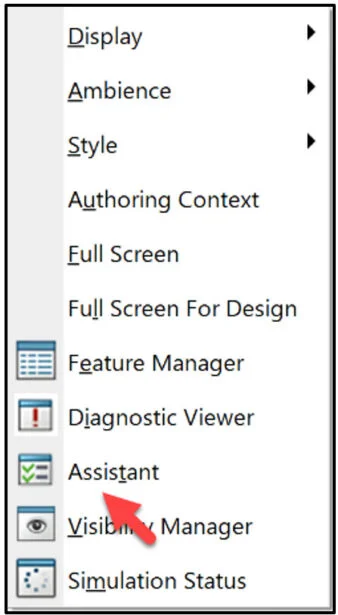
Display the Assistant dialog box.
Right-click in the Graphics area.
Click Assistant. The Assistant dialog box is display.
Click Parts from the Assistant dialog box.
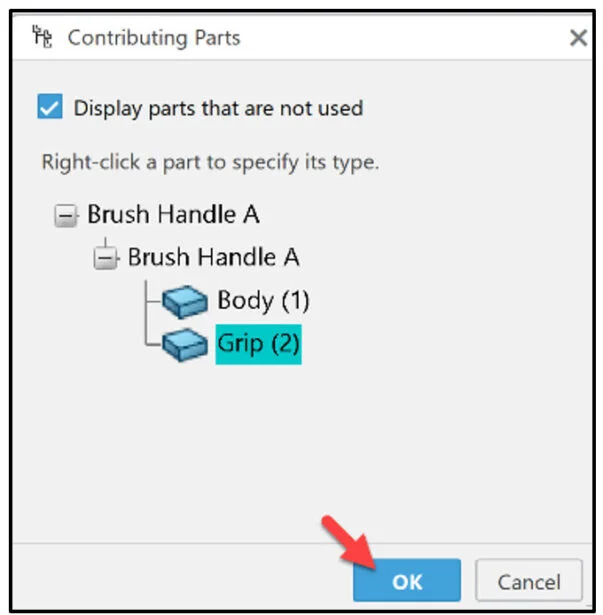
Click Contributing Parts from the Commands box.
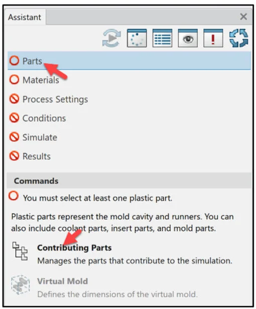
The Contributing Parts dialog box is displayed.
Assign the plastic domain to the Handle and Grip.
Right-click Body. View your domain options.
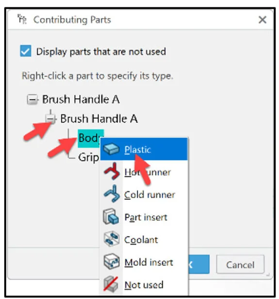
Click Plastic from the drop-down menu.
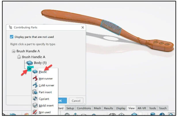
Right-click Grip as illustrated.
Click Plastic from the drop down menu. You assigned the two plastic domains for the model cavity
Select Body and Grip
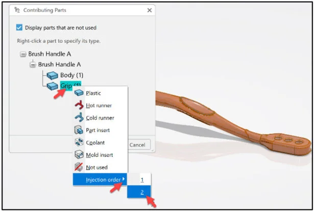
Specify the filling sequence (order in which to fill the cavities).
Fill the Body, then the Grip.
Right-click Body.
Click Injection order from the drop-down menu. Select 1.
Right-click Grip as illustrated.
Click Injection order from the drop-down menu. Select 2.
Click OK from the Contributing Parts dialog box.
View the Simulation study tree.
Apply Materials
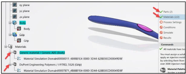
Add material to the Body. Apply Generic ABS material. Add material to the Grip. Apply DuPont™ Engineering Polymers / HYTREL ® 5526 material. Note: The materials you select must have the Injection molding behavior specified in their simulation domains.
Click Materials from the Assistant dialog box.
Click Material Palette from the Commands box. Note: You can also select Material Palette from the Setup tab in the Action bar.
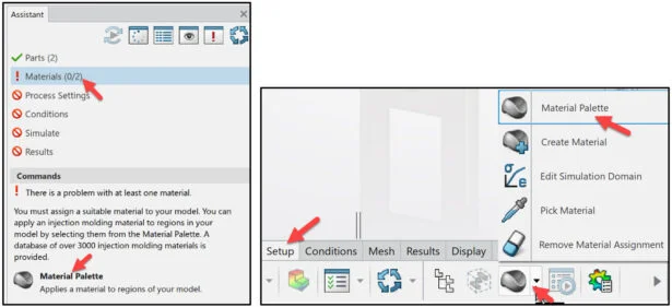
Enter Generic ABS in the Filter search box. View the results.
Select Generic material / Generic ABS | A.1. View the Simulation material properties.
Click the Simulation tab.
Return to the Core Material box.
Drag and drop Generic material / Generic ABS | A.1 onto the Body as illustrated.
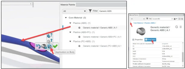
Click Application on Body from the Pop-up menu. Note: The Body icon displayed.
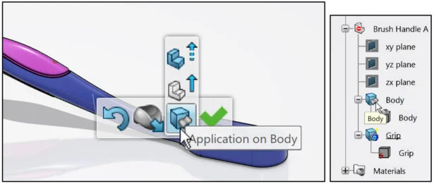
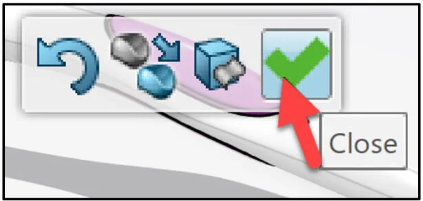
Click Close from the Pop-up menu
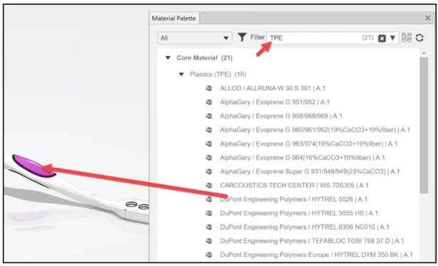
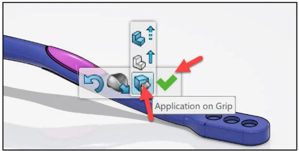
Repeat the above process to apply DuPont™ Engineering Polymers / HYTREL ® 5526 material to the Grip. Note: The material is located in the thermoplastic elastomer (TPE) family of materials.
Close the Material Palette dialog box.
View the results.
Two-Shot Mold Simulation
Define the process settings for the two-shot plastic injection molding simulation. The process setting dialog box provides the ability to control settings of the plastic injection analysis. Simulate the main plastic injection molding steps: Filling the mold cavity with a plastic material, packing a plastic material inside the cavity, and cooling the mold.
Click Process Settings from the Assistant dialog box.
Click Process Settings from the Commands box. Note: You can also select Process Settings from the Setup tab in the Action bar.
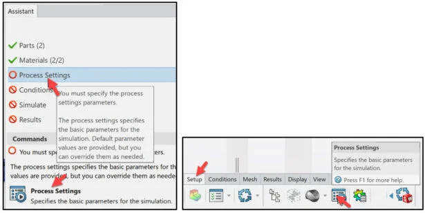
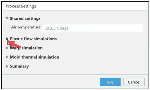
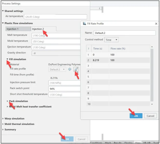
The Process Settings dialog box is displayed. View the default Shared settings and options. Accept the default Shared settings.
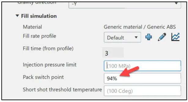
Expand the Plastic flow simulations column as illustrated .
View the options. You have two tabs: Injection 1 and Injection 2.
Click the Edit profile icon as illustrated under the Injection 1 tab. Address the injection fill rate. Fill rate profiles define the filling rate as a function of time or as a percentage of filled cavity volume.
The Fill Rate Profile dialog box is displayed.
Enter 6 in the second row under time. Click OK from the Fill Rate Profile dialog box.
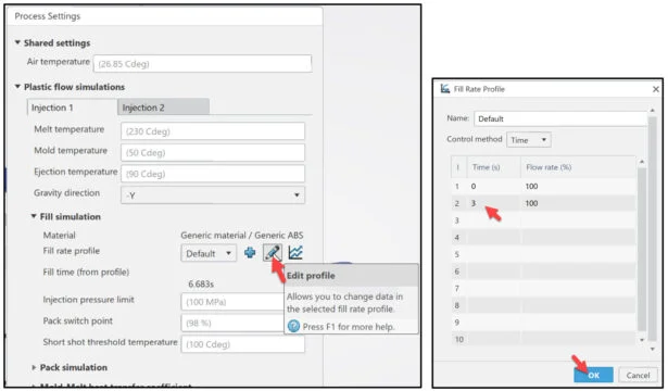
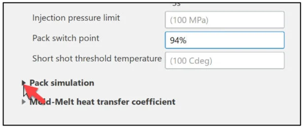
Enter 94% in the Pack switch point. The pack switch point defines the percentage of filled cavity volume at which the packing stage begins. To avoid abrupt pressure increases, it is common to begin packing just before the cavity becomes 100% full.
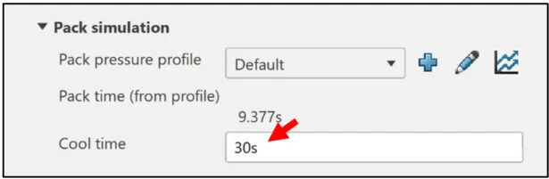
View the process settings for the Pack pressure.
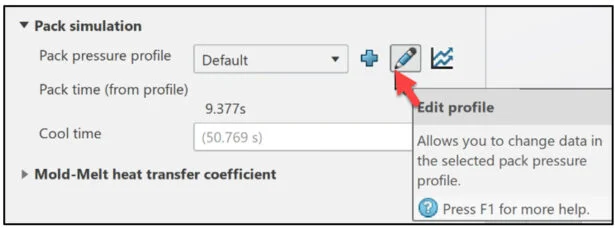
Expand Pack simulation as illustrated.
A Pack pressure profile defines the duration of the first stage of the packing analysis and the variation of pressure as a function of time.
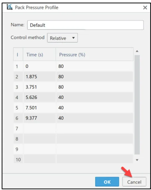
Click the Edit profile icon as illustrated.
View the default values. Accept the default values.
Click Cancel from the Pack Pressure Profile dialog box.
Cool time sets the duration of the second stage of the packing analysis, where pressure is removed and the material cools further.
Set the cool down time.
Enter 30 seconds for Cool time.
View the process for Injection 2.
Click the Injection 2 tab under the Plastic flow simulations section.
Explore the default setting. Accept the default settings.
Click OK from the Process Settings dialog box.
Injection Locations
Define two injection locations (one on the Body and one on the Grip) using two predefined surfaces. Each injection location is meant to deliver a different material in the model.
The injection unit of an injection molding machine injects molten polymer under high pressure into a mold’s cavity. Using the App, you can define each injection location by selecting a surface or a point on a plastic part.
Define the injection location on the Grip.
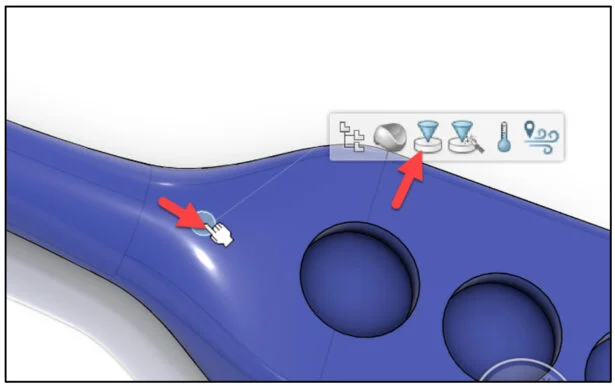
Zoom-in on the injection point (center of the circle) of the Grip.
Click a point as illustrated. A Pop-up menu is displayed. View your options.
Click the Injection Location icon from the Pop-up menu.
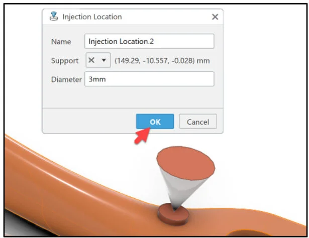
The Injection Location dialog box is displayed
Click OK from the Injection Location dialog box. View the conical glyph.
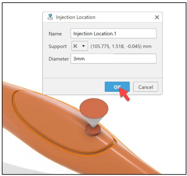
Zoom-in on the injection point (center of the circle) of the Body.
Click a point as illustrated. A Pop-up menu is displayed. View your options.
Click the Injection Location icon from the Pop-up menu.
The Injection Location dialog box is displayed
Click OK from the Injection Location dialog box. View the conical glyph.
View the two conical glyphs in the Graphics area.
Define Mesh
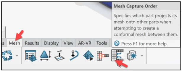
Define the mesh capture order to facilitate the creation of the conformal mesh between the Body and Grip.
Click Mesh Capture Order from the Mesh tab in the Action bar.
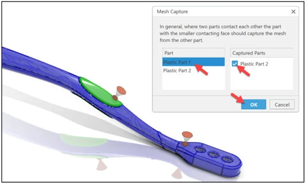
The Mesh Capture dialog box is displayed.
Select Plastic Part 1 in the Part box as illustrated. Plastic Part 2 is displayed in the Captured Parts box.
Select Plastic Part 2 in the Captured Parts box as illustrated.
Click OK from the Mesh Capture dialog box.
Refine the mesh element size.
Open the Mesh Part Manager.
Click Mesh Part Manager from the Mesh tab in the action bar.
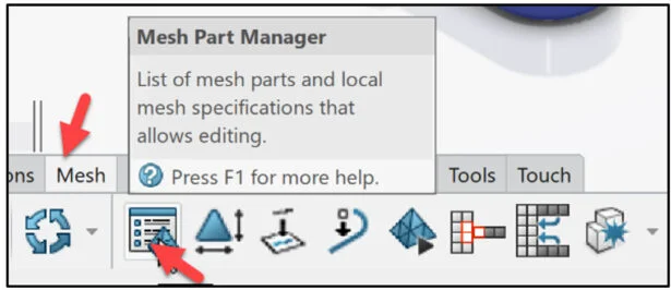
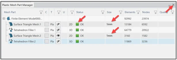
The Plastic Mesh Part Manager dialog box is displayed.
Enter 1mm for the Size of the Surface Triangle Mesh.1.
Enter 1mm for the Size of the Surface Triangle Mesh.2.
Update all items. View the OK Status. View the number of Elements and Nodes.
Close the Plastic Mesh Part Manager dialog box.
Mesh the part.
Click Create Mesh from the Mesh tab in the Action bar.
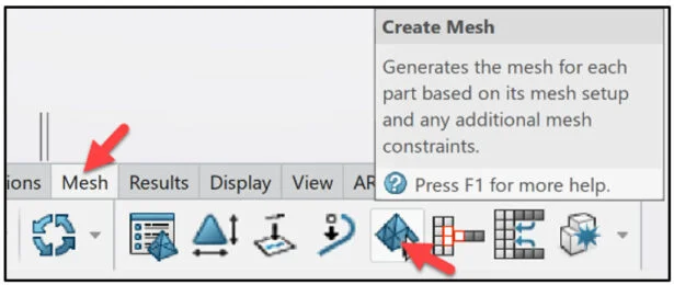
View the results in the Graphics area.
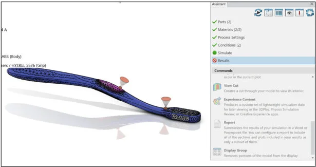
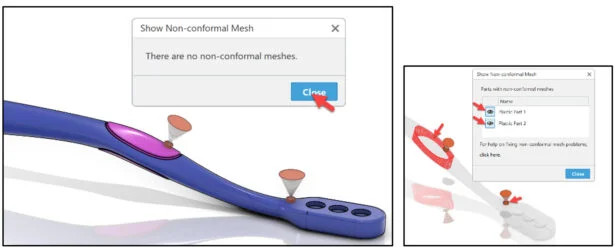
Verify that the meshes are conformal at their interface. In a model with geometries, a conformal mesh ensures that the nodes and element faces on both sides of the interface (Coincident faces) match.
Click Show Non-Conformal Meshes from the Mesh tab in the Action bar.
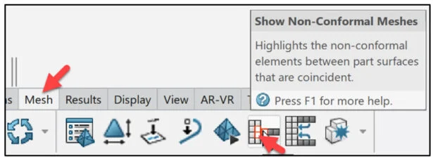
The Show Non-Conformal Mesh dialog box is displayed.
The App highlights non-conformal mesh elements in red.
Click Close from the Show Non-Conformal Mesh dialog Note: If the meshers are non-conformal, you can try switching the parts in the Mesh Capture dialog box and then regenerate the mesh. Although a conformal mesh (shared topology) improves the results accuracy, you can still successfully run a Fill, Pack, or Warp analysis that has non-conformal meshers.
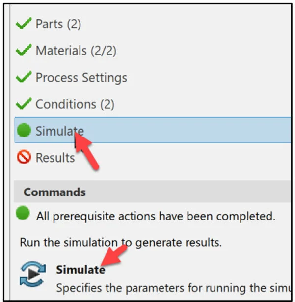
Run the Fill, Pack, and Warp analysis cases of the simulation.
Click Simulate from the Assistant dialog box.
Click Simulate from the Commands box.
Run Simulation
The Simulate dialog box is displayed. It is recommended to run the Simulation using Local interactive. Local interactive is set by default using an embedded license. The Simulation is executed on your computer and the user interface is locked while the Simulation is in process.
With an Educational license, up to 4 physical cores are supported.
Click OK from the Simulate dialog box. Run time is approximately 7 minutes.
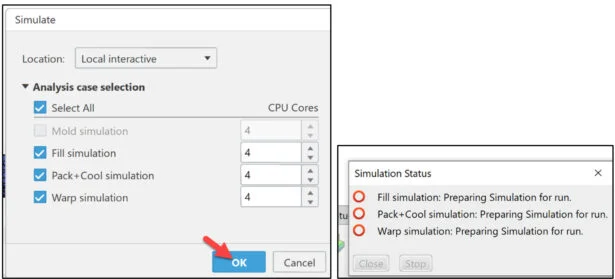
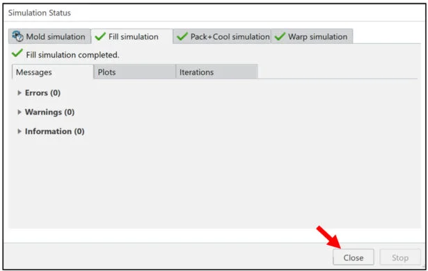
The Simulation Status dialog box is displayed. View the created simulations: Fill, Pack + Cool and Warp.
Click Close from the Simulation Status dialog box.
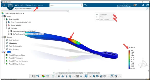
Review the pressure at the end of Pack analysis case. View the results in the Graphics window. The default contour plot is Fill time. The Fill time pot displays the time when the plastic flow front reaches each point in the model. The portion of the Brush Handle that is filled with plastic last is the end of the grip that is furthest from the grip’s injection.
Generate contour plots for the Pack Simulation.
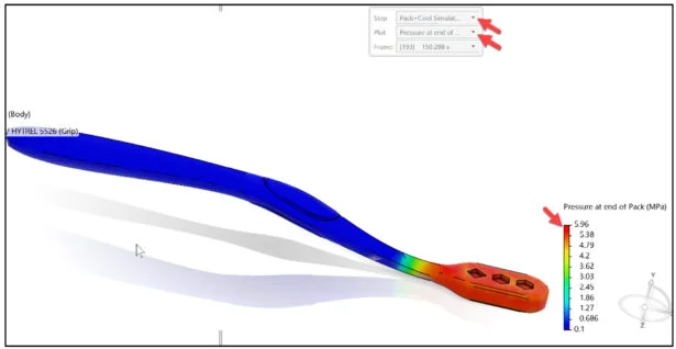
Review the pressure at the end of the Pack analysis case.
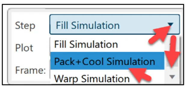
Select Pack + Cool Simulation from the Step drop-down menu as illustrated.
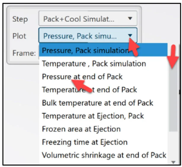
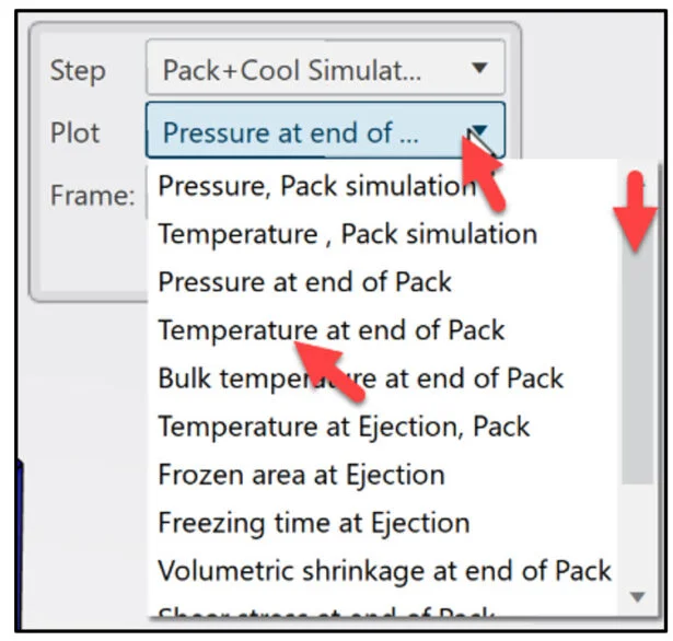
Select Pressure at end of Pack from the Plot drop-down menu.
View Results for Pressure, Temperature and Warp
During the pack stage, the injection molding machine applies additional pressure to the molten plastic to add more polymer material into the filled cavity. The additional pressure compensates for part shrinkage and reduces the occurrence of external sink marks.
Review the temperature at the end of Pack analysis case.
Select Temperature at end of Pack from the Plot drop-down menu.
Click a point on the model. The mouse cursor automatically acts as a probe. View the temperature at that point. A Pop-up menu is displayed.
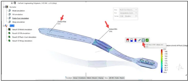
Click the Show Min/Max Values icon from the Pop-up menu.
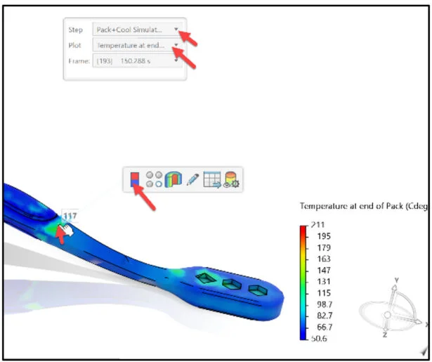
View the results.
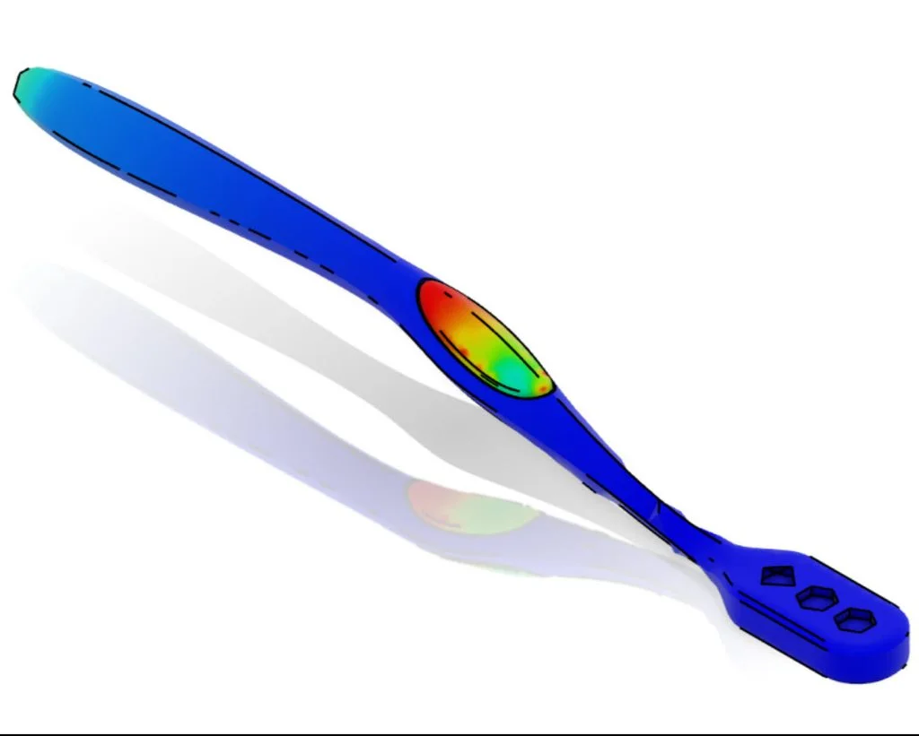
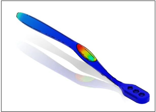
Generate a contour plot for the Warp Simulation.
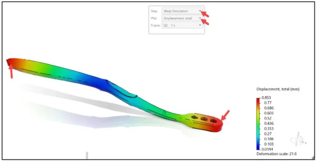
Select Warp Simulation from the Step drop-down menu.
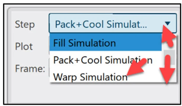
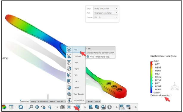
Select Displacement, total from the Plot drop-down menu.
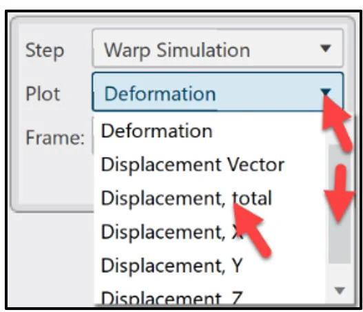
The largest displacement due to warp occurs at the head and tip of the Brush Handle. Warp occurs because of the stresses that develop during the Fill and Pack stages of the injection molding process, as well as the stresses that develop as the material contracts during cooling.
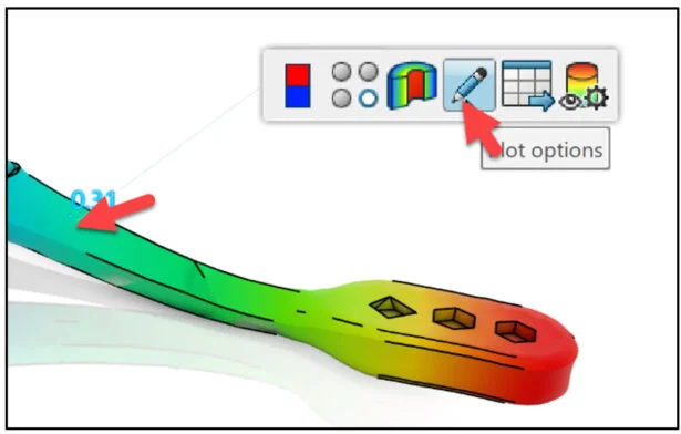
Edit the deformation scale of the displacement plot to view the deformed shape of the Brush Handle in true scale.
Click a point on the Brush Handle. A Pop-up menu is displayed.
Click the Plot options icon from the Pop-up menu.
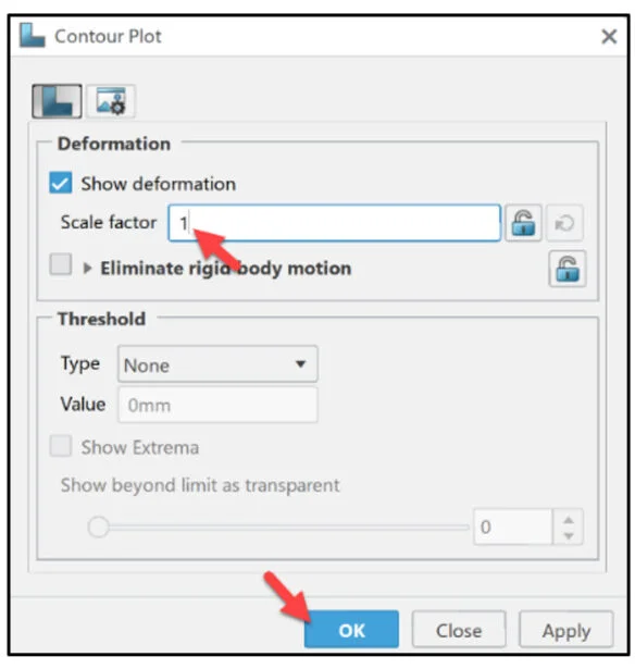
The Contour Plot dialog box is displayed.
Enter 1 for Scale factor.
Click OK from the Contour Plot dialog box.
Display an Isometric view of the Brush Handle.
Create, Play and Save Animation
Create an animation of the current contour plot (Warp Simulation – Displacement total).
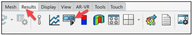
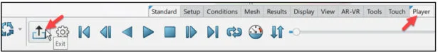
Click the Play Animation icon from the Results tab in the Action bar.
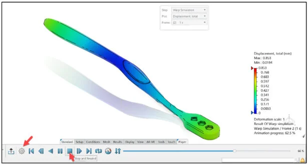
View the animation.
Click the Stop and Rewind icon.
Save the animation.
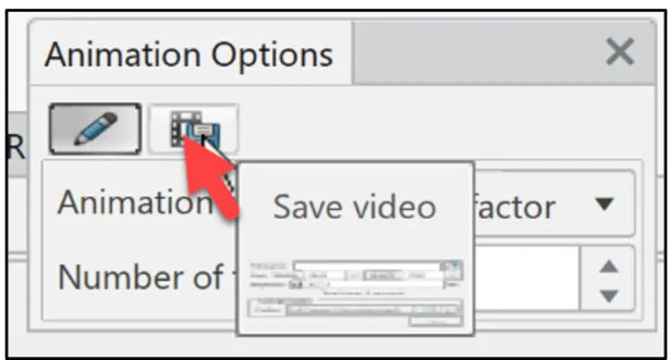
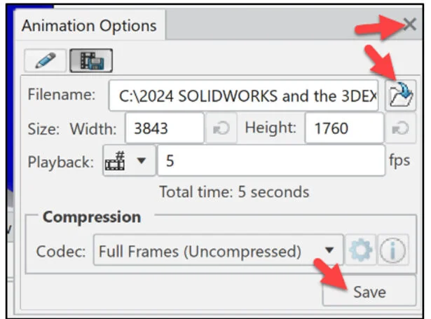
Click the Options icon.
The Animation Options dialog box is displayed.
Click the Save video icon.
Click the Open to choose browser location icon.
Select file location and name.
Click Save from the Animation Options dialog box.
Close the Animation Options dialog box.
Close the Player.
Click Exit from the Player tab in the Action bar.
Save the Simulation study (Model, Scenario, and Result).
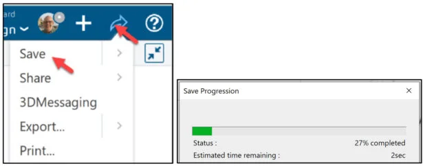
Save the Simulation study.
Click the Share icon as illustrated.
Click Save.
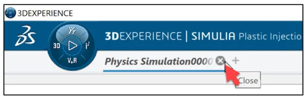
Close the Simulation study.
Click Close on the Physics Simulation tab.
The lesson is finished.
Community
Academic Community: After you create a 3DEXPERIENCE ID, Educators, can get more information on xDesign and SOLIDWORKS. Request to join the 3DEXPERIENCE Academic Community for free at go.3ds.com/academiccommunity.
Student Community: Students, join the student community for free at go.3ds.com/studentcommunity. Check out great posts on Mechanism Mondays, FEA Fridays, Solid Saturdays (animations), Formula Student and Formula SAE exercises.
SIMULIA Community: Students and Educations, join the SIMULIA community to learn the latest in simulation technology with the Abaqus solver, CST Studio Suite for Electro-magnetics, Antenna Magus and more.
SOLIDWORKS Community: Connect with the SOLIDWORKS community with our SOLIDWORKS User Forum, SOLIDWORKS User Groups, news and info,
SIMULIA Simulation Technology
Additional Lessons in 3DEXPERIENCE Simulation Structural Analysis:
Analysis Lesson 1: SOLIDWORKS and 3DEXPERIENCE Simulation for Diving Board
Analysis Lesson 2: SOLIDWORKS and 3DEXPERIENCE Simulation Linear Structural Validation Part 1
Analysis Lesson 3: SOLIDWORKS and 3DEXPERIENCE Simulation Linear Structural Validation Part 2
Analysis Lesson 4: SOLIDWORKS and 3DEXPERIENCE Simulation Linear Structural Validation for Assembly
Analysis Lesson 5: SOLIDWORKS and 3DEXPERIENCE Simulation Structural Model Creation
CFD Lesson 1: SOLIDWORKS and 3DEXPERIENCE Fluid Scenario Creation (Part1)
CFD Lesson 2: SOLIDWORKS and 3DEXPERIENCE Fluid Scenario Creation (Part 2)
CFD Lesson 3: SOLIDWORKS and 3DEXPERIENCE Fluid Scenario Creator (Part 3)
CFD Lesson 4: SOLIDWORKS Duct and 3DEXPERIENCE Fluid Scenario Creator (Part 1)
CFD Lesson 5:SOLIDWORKS Duct and 3DEXPERIENCE Fluid Scenario Creator (Part 2)
CFD Lesson 6:SOLIDWORKS Race Car and 3DEXPERIENCE Fluid Scenario Creator
Plastics Lesson 1: SOLIDWORKS Plate and 3DEXPERIENCE Plastic Injection App
From SOLIDWORKS Desktop to the 3DXPERIENCE Platform
Additional Lessons in this series on 3DEXPERIENCE Works:
3DEXPERIENCE Works Lesson 1: Getting Started with SOLIDWORKS and the Platform
3DEXPERIENCE Works Lesson 2: SOLIDWORKS and Save and Revision
3DEXPERIENCE Works Lesson 3: SOLIDWORKS and Bookmarks, Share and Delete
3DEXPERIENCE Works Lesson 4: SOLIDWORKS and Lifecycle Maturity States
3DEXPERIENCE Works Lesson 5: SOLIDWORKS, Collaborative Space and Bookmarks
3DEXPERIENCE Works Lesson 6: SOLIDWORKS with Search Tools
3DEXPERIENCE Works Lesson 7: SOLIDWORKS with 3DPlay
3DEXPERIENCE Works Lesson 8: SOLIDWORKS with 3DDrive
3DEXPERIENCE Works Lesson 9: SOLIDWORKS and 3DSWYM
3DEXPERIENCEWorks Lesson 10: SOLIDWORKS and 3DEXPERIENCE Simulation
Cloud Apps by SOLIDWORKS (100% Browser Based)
Additional Lessons in this series on SOLIDWORKS xDesign
SOLIDWORKS xDesign Lesson #1: Getting Started
SOLIDWORKS xDesign Lesson #2: Mouse Control and Collaborative Space
SOLIDWORKS xDesign Lesson #3: Sketch Planes
SOLIDWORKS xDesign Lesson #4: Create A Dashboard
SOLIDWORKS xDesign Lesson #5: Views and Orientations
SOLIDWORKS xDesign Lesson #6: Importing Files and Using Bookmarks
SOLIDWORKS xDesign Lesson #7: Assemblies
SOLIDWORKS xDesign Lesson #8: 4Bar Linkage and Kinematics
SOLIDWORKS xDesign Lesson #9: External References and Copy with Mates
SOLIDWORKS xDesign Lesson #10: Sketching, Constraints and Dimensions
SOLIDWORKS xDesign Lesson #11: Sketch Based and Applied Features
Design well. Marie