
After teaching 1000’s of students and writing about SOLIDWORKS and SOLIDWORKS Simulation for over 25 years, David Planchard, emeritus WPI, is exploring 3DEXPERIENCE Simulation and the Abaqus solver. Through the SOLIDWORKS and 3DEXPERIENCE Simulation Lesson series, David helps educators understand 3DEXPERIENCE Simulation fundamentals through simple examples and industry practices.
I ask my students, what is the objective of Structural Design? I tell them that Structural Design simply ensures that a component will not fail when it is subjected to the loads it was designed to withstand. An understanding of Stress limits is required. Strain limits are important, but will not be addressed in this lesson.
In the previous, Analysis Lesson 2 SolidWorks and 3DEXPERIENCE Simulation Linear Structural Validation Part 1, we learned the proper workflow to upload a SOLIDWORKS part to the 3DEXPERIENCE platform and perform a Linear Structural Simulation study using the Abaqus solver. The Linear Structural Validation App was launched from the SOLIDWORKS Task Pane.
Simulation study solver preferences were addressed. Study conditions were applied: (Mesh type, Material, Fixed Displacement Restraint and Load using the Action bar and the Assistant dialog box. Three contour plots were created: Von Mises Stress, Displacement, and Factor of Safety (FOS). The Simulation Study results were analyzed and saved to a Collaborative space in a Bookmark.
In this lesson, locate the Linear Structural Simulation study in your Collaborative space with the 3DSpace widget. Launch the Linear Structural Validation App.
Modify the results storage from the server on the platform to your computer. Discover the default storage folder location on a local Window’s machine.
Modify the original load from 13300N to 23300N. Create new Simulation study contour plots. Review the plots to interpret the results.
Modify the original material from Alloy Steel to 6061 Alloy. Create new Simulation study contour plots. Review the plots to interpret the results.
Play and save a Simulation contour plot animation. Save the animation. Compare results of four Simulation study contour plots (Von Mises Stress, Factor of Safety, Reaction Force and Displacement).
Create a Simulation report. Save the report. View various Simulation help options.
Before we start, there are a few items that you need to know.
In this lesson, use your default Collaborative space. An internet connection is required. A 3DEXPERIENCE ID is required.
The Simulation lesson provides a foundation to users who are new to using simulation to solve real-word engineering and design problems. A Solid body is used. You should have a basic understanding of Stress and Finite Element Method (FEM).
Complete Analysis Lesson 2: SOLIDWORKS and 3DEXPERIENCE Simulation Linear Structural Validation (Part 1) to follow along with this lesson.
A full installation of SOLIDWORKS 2019 SP0 or later is required
Start SOLIDWORKS and Login to 3DEXPERIENCE platform
Start a SOLIDWORKS desktop session. Log into the 3DEXPERIENCE platform.
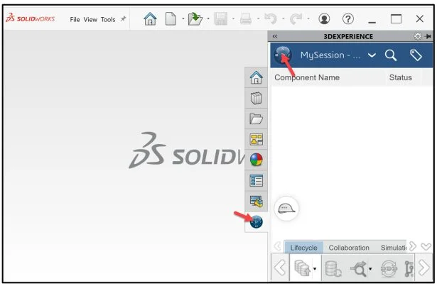
Click the Center of the Compass in the MySession panel.
Use the 3DSpace widget to view your Collaborative space, review 3DEXPERIENCE Works Lesson 5: SOLIDWORKS,Collaborative Space and Bookmarks.
Locate the Static Linear Simulation study (Model, Scenario and Result) from Lesson 2 Part 1. Open the Linear Structural Validation App. Drag the slider downward to view the 3DSpace widget.
Click the 3DSpace widget. Log into the 3DEXPERIENCE platform.
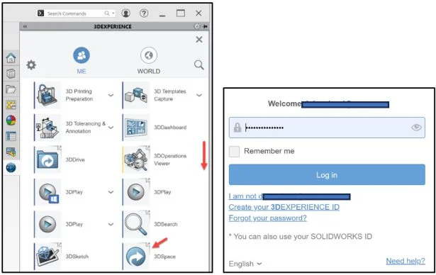
Your 3DEXPERIENCE | 3DDashboard is displayed.
In Lesson 2 Part 1, I saved the Linear Simulation study (Model, Scenario and Result) in my Quick Start xDesign Collaborative space.
Double-click your Collaborative Space as illustrated.
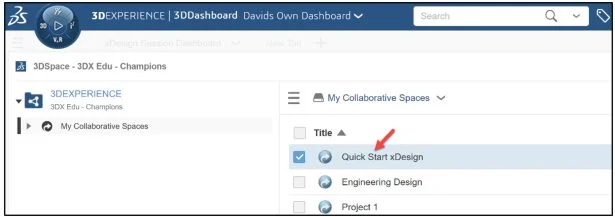
Locate the Simulation study for Model 8-6.
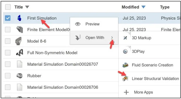
The title of the Simulation study was First Simulation.
Right-click First Simulation. A Pop-up menu is displayed.
Expand Open With. View your options.
Linear Structural Validation App
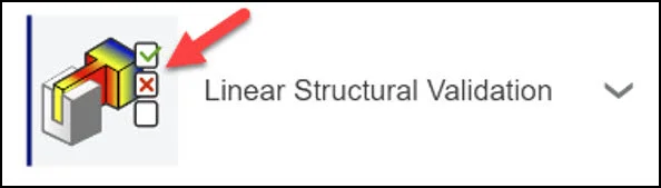
Launch the Linear Structural Validation App.
Click Linear Structural Validation.
This can take 5 – 10 seconds.
Click Restore if needed.
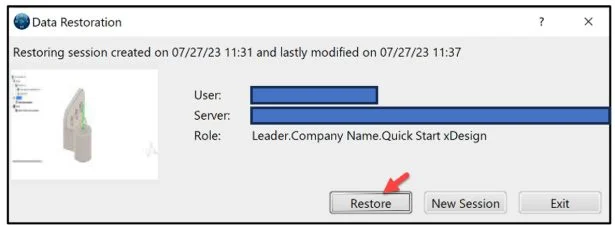
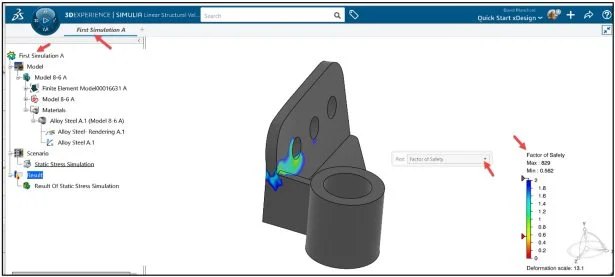
First Simulation A is displayed.
Center the model if needed. View the Triad position.
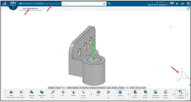
Display the Simulation study tree.
Right-click in the Graphics area.
Click Display.
Click Tree Display. The Simulation study tree is displayed.
Expand the Result folder.
Double-click the Result Of Static Stress Simulation in the Result folder.
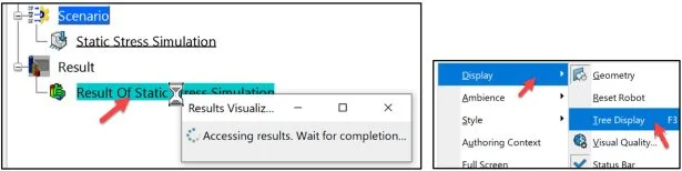
The last Simulation study contour plot from Lesson 2 Part 1 is displayed.
Model and Scenario data is always stored on the 3DEXPERIENCE server in your Collaborative space.
Results Storage
Result data may be stored on the server or in a local directory on your machine. Local data is masked, encrypted and only accessible by the owner of the data.
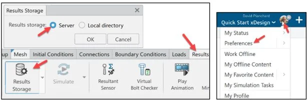
Click the Results tab in the Action bar.
Click Results Storage. The Results Storage dialog box is displayed.
The default option is Server on the platform. Saving the Simulation Result data from a Simulation on the server allows other users in your Collaborative space to access that data and archive the data for future reference.
Improve computation and postprocessing performance by saving the Simulation study result in a Local directory. Note: Set your Local directory file location under Preferences.
Save the Simulation study Result data to a folder on your local computer.
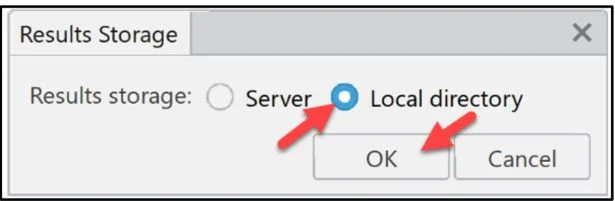
Select Local directory from the Results Storage dialog box.
Click OK from the Results Storage dialog box.
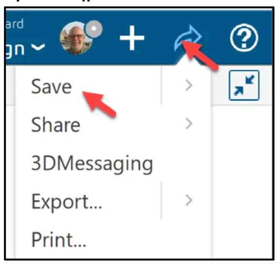
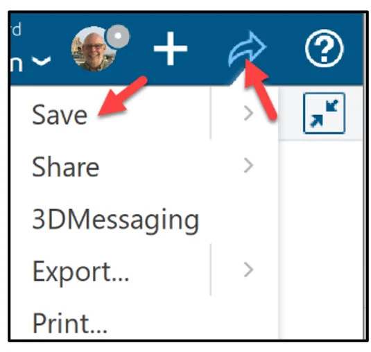
Click Share icon as illustrated.
Click Save.
The default location for a non-network Windows machine with a single hard drive is C:UsersWinUsernameAppDataLocalDassaultSystemesPLM_LocalResults.
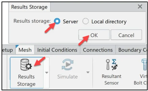
Return to the default save location on the 3DEXPERIENCE platform.
Click the Results tab in the Action bar.
Click Results Storage. The Results Storage dialog box is displayed.
Select Server.
Click OK from the Results Storage dialog box.
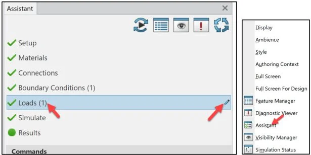
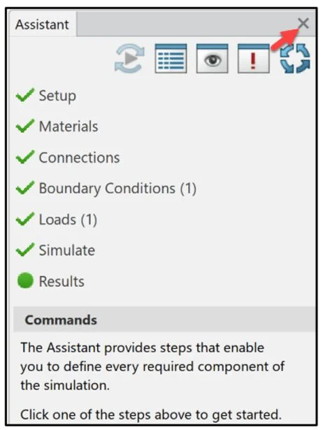
Display the Assistant dialog box.
Right-click Assistant in the Graphics area. The Assistant dialog box is displayed.
Modify Load
Modify the applied translational load on the flat face from 13300N to 23300N.
Click Loads (1) in the Assistant dialog box.
Double-click the Edit icon as illustrated.
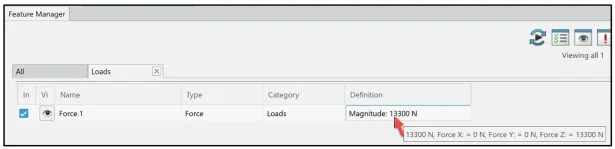
The Feature Manager dialog box is displayed.
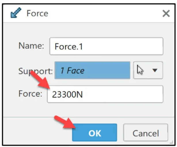
Double-click Magnitude: 13300N for Definition.
The Force dialog box is displayed.
Enter 23300N.
Click OK.
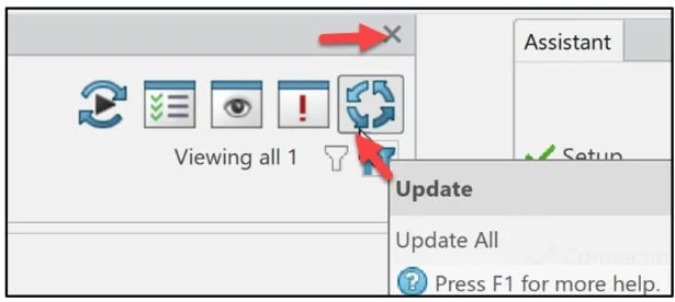
Click Update from the Feature Manager dialog box.
Close the Feature Manager dialog box.
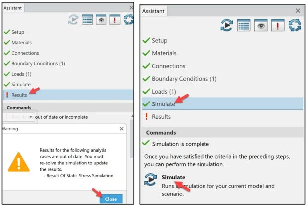
Click Results in the Assistant dialog box. The results of the analysis are out of date due to the load modification. Close the Warning box.
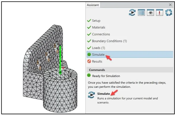
Simulate
Run the Simulation study.
Click Simulate from the Assistant dialog box.
Click Simulate from the Commands box.
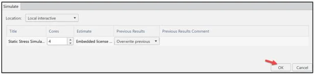
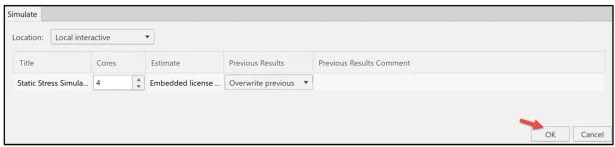
The Simulate dialog box is displayed. For a new user, It is recommended to run the Simulation using Local interactive. Local interactive is set by default using an embedded license. The Simulation is excuted on your computer and the user interface is locked while the Simulation is in process. Using an Educational license, up to 4 physical cores are supported. Note: Overwrite previous is selected by default.
Click OK.
The Simulation Status dialog box is displayed.
The Static Stress Simulation is completed with the new load (23300N).
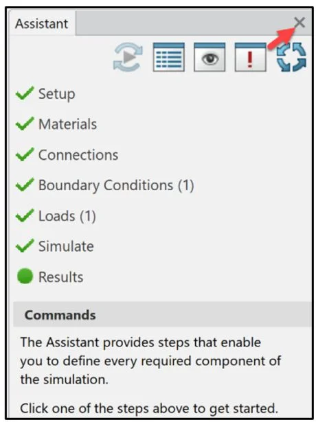
Click Close Simulation Status dialog box.
Close the Assistant dialog box.
Factory of Safety Plot
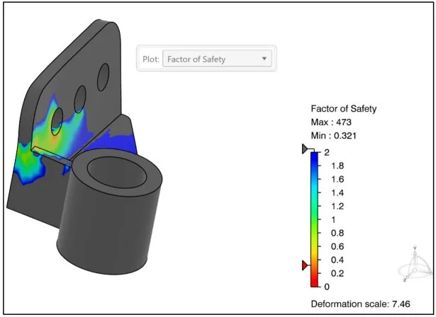
Review the Factor of Safety (FOS) contour plot to identify the critical regions of the model. The FOS plot displays how close a material is to yielding. The Factor of Safety is calculated by dividing the material’s Proof (Yield) Strength by the Allowable stress.
The FOS plot has a maximum limit of 2 by default. Regions of the model with a FOS larger than 2 are shown in gray.
The old Factor of Safety (FOS) range: Min: .562 – Max: 829.
The new Factor of Safety (FOS) range: Min: .321 – Max 473.
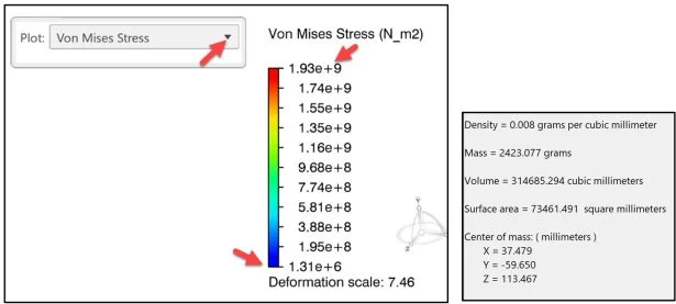
Von Mises Stress Plot
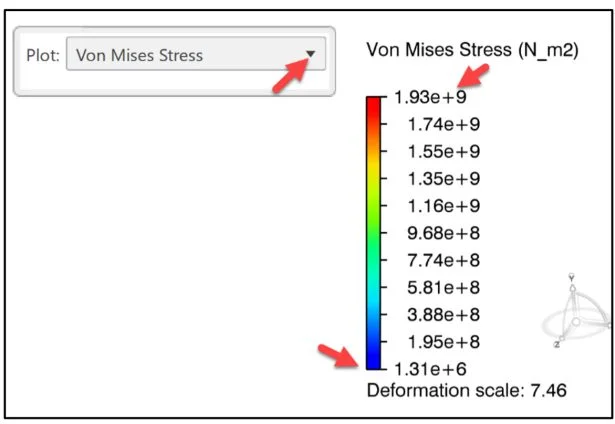
Display the Von Mises Stress contour plot with the new load (23300N).
Verify that the Von Mises stresses do not exceed the material’s yield strength. For most metals, the yield strength is defined as the stress point at 0.2% strain offset. For Alloy Steel this is (6.204 × 10⁸N/m2).The maximum Von Mises stress (1.93 × 10⁹N/m2) is above the material’s yield strength of (6.204 × 10⁸N/m2).
Below is the Von Mises Stress contour plot with the original load (13300N).
Finite Element Analysis (FEA) has been used for decades to help designers and engineers understand how parts and the materials they are made from behave in real life. In most cases, the analyst is looking for stresses that exceed yield or strain higher than the failure rating of the material.
Most parts are incorporated into subassemblies. Other important factors for designs are cost and overall weight of the final assembly.
In the next section, modify (lower) the overall mass of the material and rerun the Simulations study to evaluate Structural integrity.
Modify Applied Material
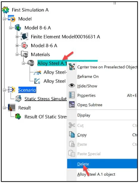
Delete the current applied material.
Right-click Alloy Steel as illustrated in the Simulation Study tree.
Click Delete from the drop-down menu.
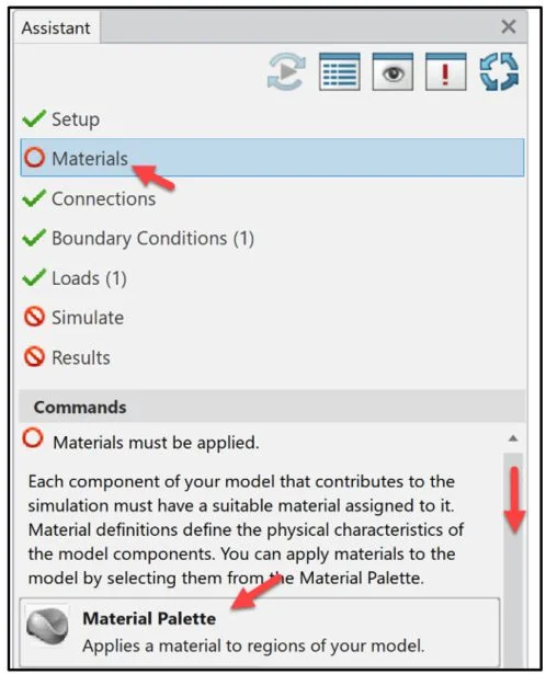
The Assistant dialog box displays that a material is required.
Click Materials from the Assistant dialog box.
Drag the slider downward to view the Material Palette.
Click Material Palette from the Assistant dialog box.
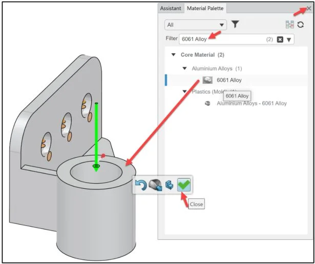
The Material Palette dialog box is displayed.
Enter 6061 Alloy in the Filter Search box. Your material library maybe different than illustrated.
Drag and drop 6061 Alloyon the model.The material is applied.
Click the green checkmark from the Pop-up menu.
Close the Material Palette dialog box.
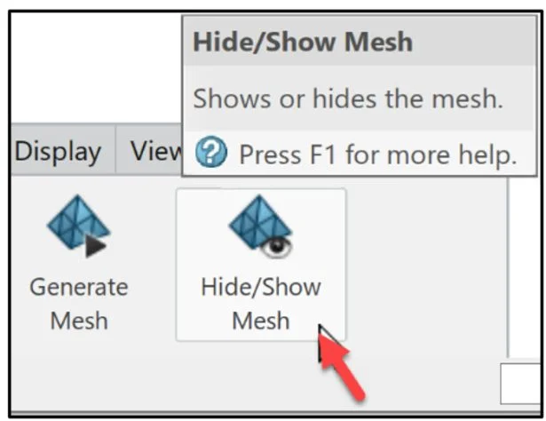
Display the Mesh on the model.
Click Hide / Show Mesh from the Results tab in the Action bar.
Display the Assistant dialog box.
Right-click in the Graphics area.
Click Assistant.
The Assistant dialog box is displayed.
The present Results are not valid. Run a Simulation study.
Click Simulate from Assistant dialog box.
Click Simulate from the Commands box.
The Simulate dialog box is displayed.
Click OK.
The Simulation Status dialog box is displayed.
Click Close.
Close the Assistant dialog box.
Review Results
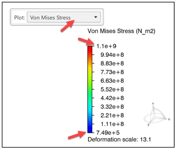
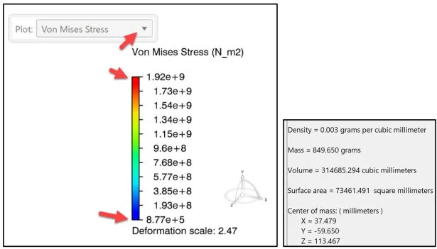
Display the Von Mises Stress contour plot with the new material (6061 Alloy).
Verify that the Von Mises stresses do not exceed the material’s yield strength. For most metals, the yield strength is defined as the stress point at 0.2% strain offset. For 6061 Alloy this is (5.157 × 10⁷N/m2).The maximum Von Mises stress (1.92 × 10⁹N/m2) is above the material’s yield strength of (5.157 × 10⁷N/m2).
The mass of the part is 849.65 grams.
Below is the Von Mises Stress contour plot with the old material (Alloy Steel).
Verify that the Von Mises stresses do not exceed the material’s yield strength. For most metals, the yield strength is defined as the stress point at 0.2% strain offset. For Alloy Steel this is (6.204 × 10⁸N/m2).The maximum Von Mises stress (1.93 × 10⁹N/m2) is above the material’s yield strength of (6.204 × 10⁸N/m2).
The mass of the part is 2423.08 grams.
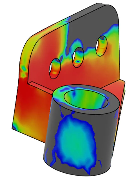
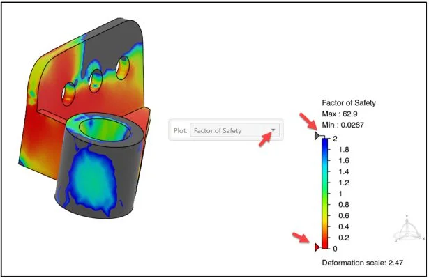
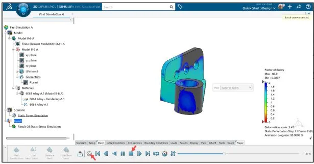
Display the Factor of Safety (FOS) contour plot.
Regions of the model with a FOS less than 1 develop stresses above the material’s yield strength under the current loading conditions.
The smallest factors of safety occur in the localized regions where the highest Von Mises stresses occur.
The range is between 0.0287 and 62.9. This plot is concerning due to the amount of area with a FOS below 1.

Further investigation of material and or the design would be highly recommended.
Save the Simulation study.
Click the Share icon as illustrated.
Click Save.
Animation
Click Play Animation from the Results tab in the Action bar.
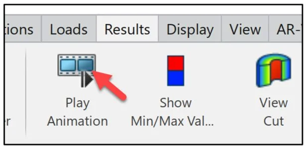
View the Animation.
Click the Stop and Rewind button.
Record the animation.
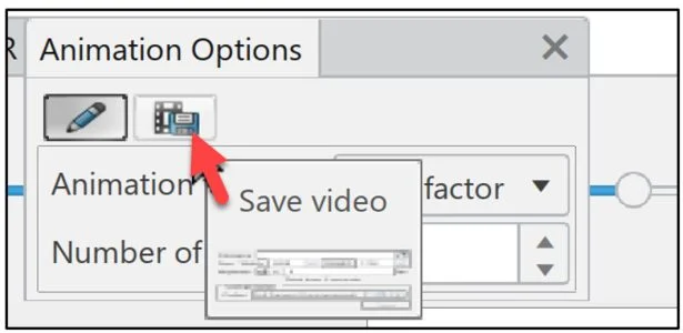
Click the Option button.
The Animation Options dialog box is displayed.
Click the Save video icon as illustrated.
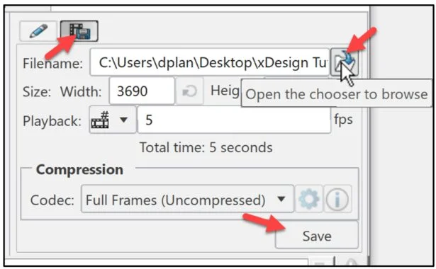
The Animation Options dialog box is displayed.
Click the Open the chooser to browser icon.
Select a folder location on your computer.
Enter the name of the avi file.
Click Save.
Close the Animation Options box.
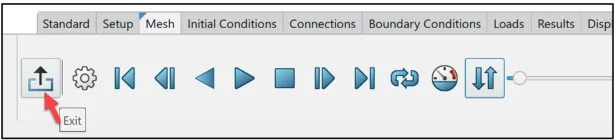
Close the Player.
Click Exit.
Compare Results Plots
Compare four Simulation contour plots (Factor of Safety, Von Mises Stress, Reaction Force and Displacement).
Click Compare Results from the Results tab in the Action bar.
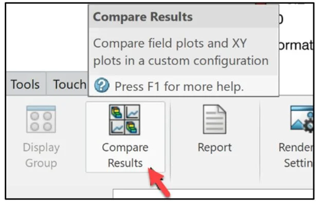
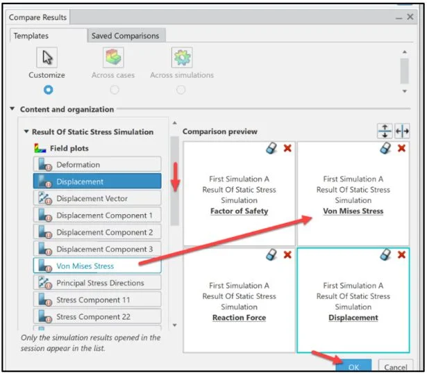
The Compare Results dialog box is displayed. There are two tabs: Templates and Saved Comparisons. The default tab is Templates.
The Factor of Safety contour plot is active.
Drag and drop the Von Mises Stress, Reaction Force and Displacement as illustrated in the Comparison boxes.
Click OK. Note: In SOLIDWORKS Simulation the URES Resultant Displacement and the Displacement in 3DEXPERIENCE Simulation represent the same displacement components. Displacement Component 1, 2 and 3 in 3DEXPERIENCE Simulation represent the same displacement components as UX, UY and UZ in SOLIDWORKS Simulation.
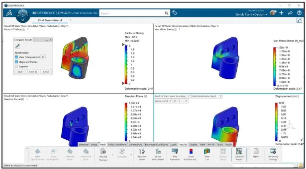
Four Simulation contour plots are displayed.
The Compare Results dialog box is displayed.
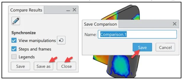
Save the Simulation contour plot comparisons.
Click Save as. The Save Comparison dialog box is displayed. The default name for the first Comparison is Comparison.1. Accept the default name.
Click Save.
Click Close from the Compare Results dialog box.
Results Report
Generate a report of the Simulation study.
Click Report from the Results tab in the Action bar.
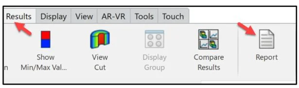
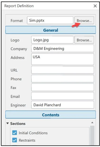
The Report Definition dialog box is displayed. View the Sections and Results under the Contents tab. Click the General tab. View your options.
Click the Browse button in the Format row to locate the Word Document template or PowerPoint template on your local machine.
The default location for the report templates (for a non-network Windows machine with a single hard drive) is: This PCWindow (C:)Program FilesDassault SystemsB425_Cloudwin_b64refiflesSimulationProductsReportTemplates.
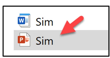
Select the report PowerPoint template.
Double-click the Sim PowerPoint template icon.
Save and generate the Simulation study report.
Click OK from the Report Definition dialog box.
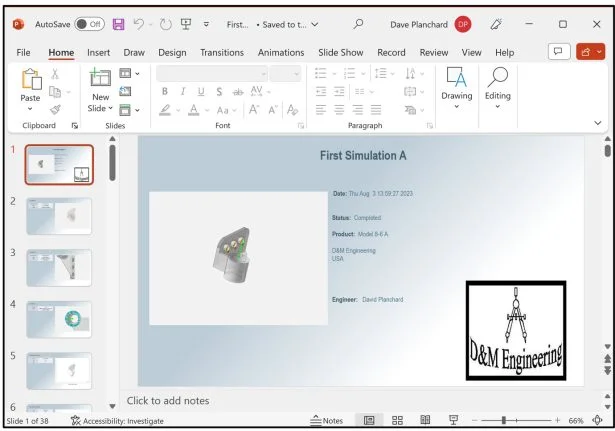
The Simulation report is displayed. Review the report.
Save the report. Close the report.
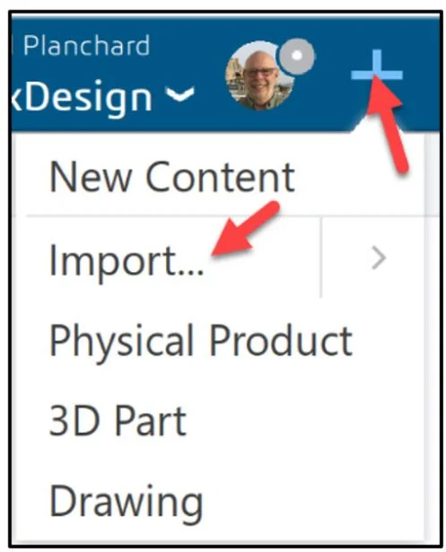
Click the Plus icon as illustrated.
View the drop-down menu. Important! For SOLIDWORKS models do not use the Import option. Follow the steps shown in Lesson 2 Part 1 to keep the association between your SOLIDWORKS model and 3DEXPERIENCE Simulation study on the platform.
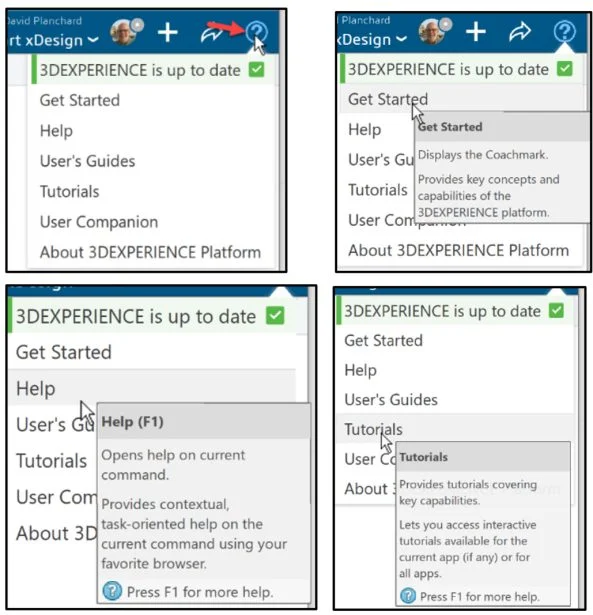
Help and Get Started
Click the Help icon.
View your options.
Save the Simulation study.
Click the Share icon as illustrated.
Click Save.
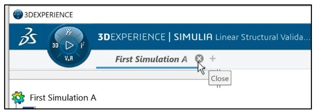
Close the Simulation study.
Click Close on the First Simulation A tab.
We are finished with this lesson.
3DEXPERIENCE Communities:
Academic Community: After you create a 3DEXPERIENCE ID, Educators, can get more information on SOLIDWORKS and the 3DEXPERIENCE Platform. Request to join the 3DEXPERIENCE Academic Community for free at go.3ds.com/academiccommunity.
Student Community: Students, join the student community for free at go.3ds.com/studentcommunity. Check out great posts on Mechanism Mondays, FEA Fridays, Solid Saturdays (animations), Formula Student and Formula SAE exercises.
Additional tutorials and lessons:
My SolidWorks and 3DEXPERIENCE Edu Space.
Additional Lessons in 3DEXPERIENCE Simulation Series:
Analysis Lesson 1: SOLIDWORKS and 3DEXPERIENCE Simulation for Diving Board
Analysis Lesson 2 : SOLIDWORKS and 3DEXPERIENCE SImulation Linear Structural Validation Part 1
Additional Lessons in this series on 3DEXPERIENCE Works:
3DEXPERIENCE Works Lesson 1: Getting Started with SOLIDWORKS and the Platform
3DEXPERIENCE Works Lesson 2: SOLIDWORKS and Save and Revision
3DEXPERIENCE Works Lesson 3: SOLIDWORKS and Bookmarks, Share and Delete
3DEXPERIENCE Works Lesson 4: SOLIDWORKS and Lifecycle Maturity States
3DEXPERIENCE Works Lesson 5: SOLIDWORKS, Collaborative Space and Bookmarks
3DEXPERIENCE Works Lesson 6: SOLIDWORKS with Search Tools
3DEXPERIENCE Works Lesson 7: SOLIDWORKS with 3DPlay
3DEXPERIENCE Works Lesson 8: SOLIDWORKS with 3DDrive
3DEXPERIENCE Works Lesson 9: SOLIDWORKS and 3DSWYM
3DEXPERIENCEWorks Lesson 10: SOLIDWORKS and 3DEXPERIENCE Simulation
Additional Lessons in this series on SOLIDWORKS xDesign:
SOLIDWORKS xDesign Lesson #1: Getting Started
SOLIDWORKS xDesign Lesson #2: Mouse Control and Collaborative Space
SOLIDWORKS xDesign Lesson #3: Sketch Planes
SOLIDWORKS xDesign Lesson #4: Create A Dashboard
SOLIDWORKS xDesign Lesson #5: Views and Orientations
SOLIDWORKS xDesign Lesson #6: Importing Files and Using Bookmarks
SOLIDWORKS xDesign Lesson #7: Assemblies
SOLIDWORKS xDesign Lesson #8: 4Bar Linkage and Kinematics
SOLIDWORKS xDesign Lesson #9: External References and Copy with Mates
SOLIDWORKS xDesign Lesson #10: Sketching, Constraints and Dimensions
SOLIDWORKS xDesign Lesson #11: Sketch Based and Applied Features
Design well, Marie