
After teaching 1000’s of students and writing about SOLIDWORKS for over 25 years, David Planchard, emeritus WPI, is exploring xDesign. Through the SOLIDWORKS xDesign Lesson series, David helps educators understand the differences and similarities between xDesign and SOLIDWORKS through simple examples. He also introduces new apps in the engineering design process.
Create assemblies using the Bottom-up design approach, the Top-down design approach, or a combination of both methods. SOLIDWORKS uses both Bottom-up and Top-down design approaches. In the Top-down approach, when you create a part in-context, the part is virtual. The virtual part does not exist outside of the assembly.
xDesign is based on a systems engineering approach (single modeling environment) which is Top-down. The Physical Products (components) can be used between many apps on the 3DEXPERIENCE platform. In xDesign, the term component is used because both parts and assemblies are treated the same.
In this lesson, download the required xDesign components. Extract and import the xDesign components: (4Bar Linkage-2 and Long Pin) into your Collaborative space.
Create an assembly called External References. In xDesign, a Root component is the top-level component. Insert the 4Bar Linkage-2 component (sub-assembly). By default, when you create a sub-assembly, it is rigid. Within the Parent component, the sub-assembly acts as a single unit and its components do not move relative to each other. However, you can make sub-assemblies flexible. This allows movement of the individual components of a sub-assembly within the Parent or Root component.
Create a Pin in the 4Bar Linkage-2 sub-assembly. Utilize the Insert New Component tool from the Assembly tab.
Insert the imported xDesign Long Pin component into the 4Bar Linkage-2 sub-assembly. Apply the Insert tool from the Assembly tab. Apply standard mates (Concentric, Coincident) to address the degrees of freedom DOFs.
Apply the Copy with Mates tool using the Long Pin component to two different locations.

Login to the 3DEXPERIENCE platform.
Start xDesign.
Click xDesign to launch the App or open an existing Dashboard with xDesign as a Widget.
Create a new Physical Product called External References.
Click the 4BAR Linkage-2 to extract the components and follow along.
Import the xDesign components: (4Bar Linkage-2 and Long Pin) into your Collaborative space. Note: A Windows model file cannot be directly opened in xDesign. The model file needs to be imported.
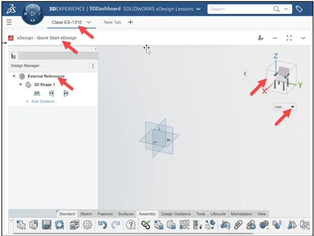
In this lesson, my Collaborative space is Quick Start xDesign.
I created a Tab for an xDesign class, ES-1310.
The default units are in millimeters.
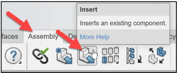
Insert the first component (sub-assembly), 4Bar Linkage-2.
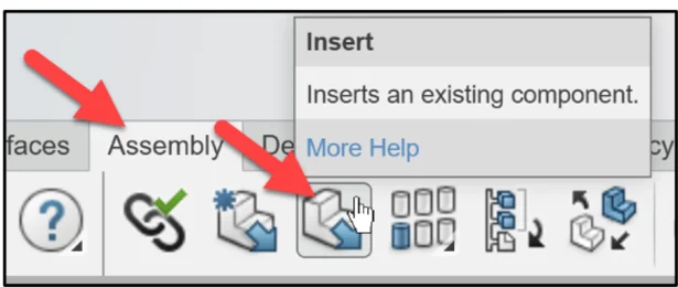
Click Insert from the Assembly tab in the Action bar.
The Open box is displayed. Use Search and the 6WTags to find the imported xDesign components. Note: 6WTags are a way to filter content. 6WTags can be used directly in your 3DSpace app or for filtering search results. There are 5 main categories: What, Where, Who, When & How. Each of these categories has a number of fields that can be used to filter your search results or all of your data in a Collaborative space.
Enter 4Bar Linkage-2 in the Search box.
Click Search.

Click inside the 4Bar Linkage-2 box from the Results area.
Click OK.
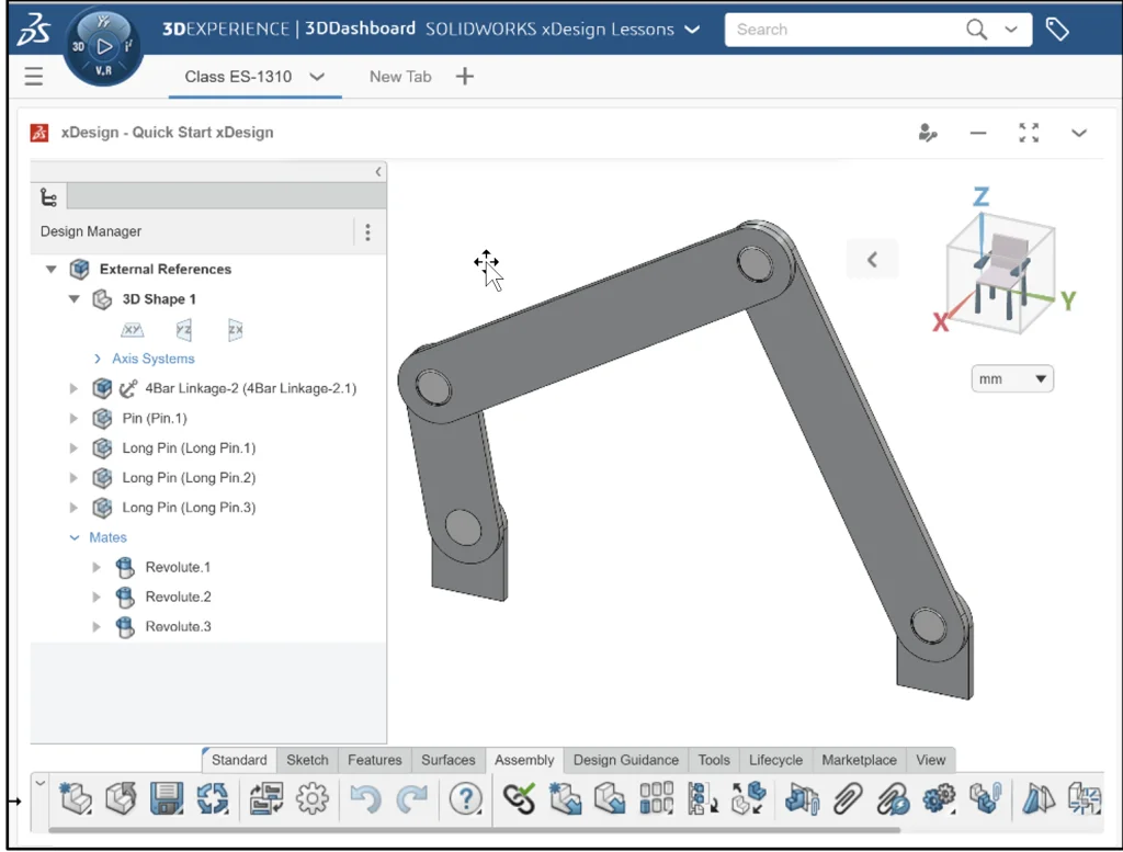
4Bar Linkage-2 is inserted to the Origin. The first component is fixed aligned to the three default planes. Note: Components can be a single solid body, multiple solid bodies or an assembly. When an assembly is inserted, it’s called a sub-assembly.
Create geometry while working in an assembly. Use the Insert New Component tool.
The Insert New Component tool provides the ability to reference existing geometry while creating new sketches and features. It also lets you borrow edges and faces to construct new geometry.
Activate the External References tool to link the created new geometry and maintain the references with changes. De-activate the External References tool (reference geometry is still created) but the geometry is not updated with new changes.
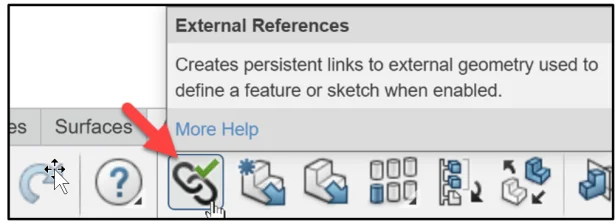
Activate the External References tool.
Click External References from the Assembly tab.
Click Insert New Component from the Assembly tab.
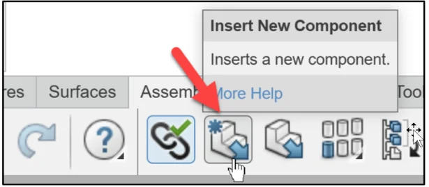
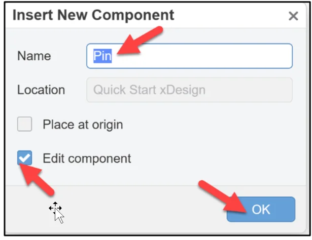
The Insert New Component dialog box is displayed.
Enter Pin for Name. Accept Edit component for option. The Edit Component option provides the ability to edit the component after inserting it.
Click OK.
Click a position in the Work Area. View the results.
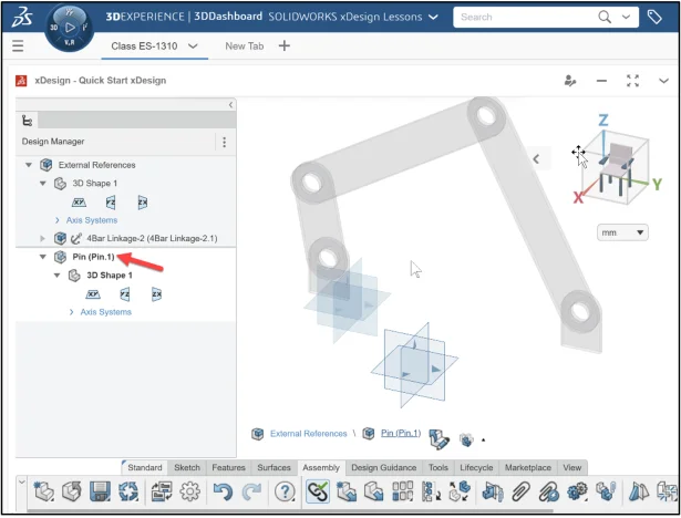
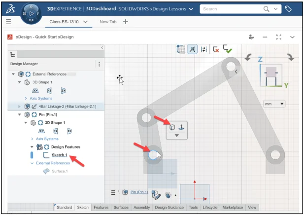
The new component (Pin) is active. You have the ability to edit the component in the Work Area. In the Design Manager, a new component is displayed without geometry. In the Work area, all other components are transparent.
Note: When a component in the assembly is active, there are visual changes: The active component is visible and the color is retained. All non-active components are transparent. The active component Design Manager background is white.
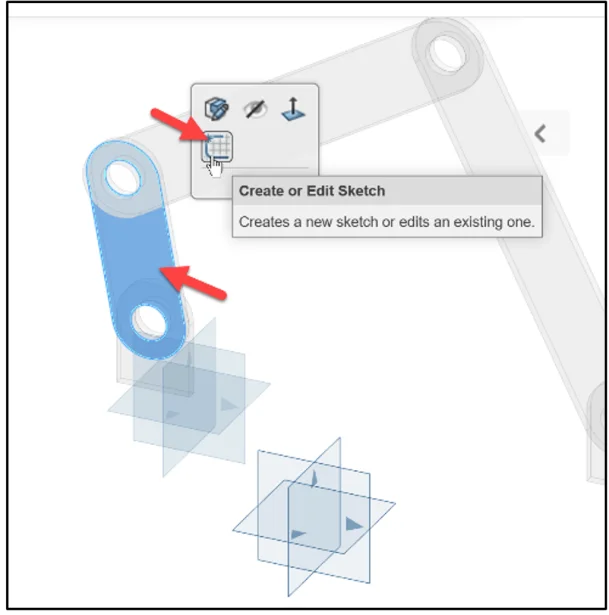
Create geometry for the Pin. Start with a sketch.
Click Part.2 in the Work Area.
Click Create from the Content box.
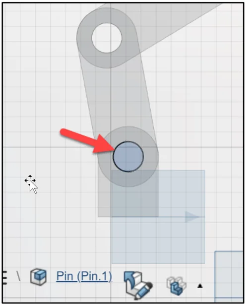
Click the outside circular edge of the first hole on Part.2
Click Convert Entities from the Content box in the Work Area.
View the results.
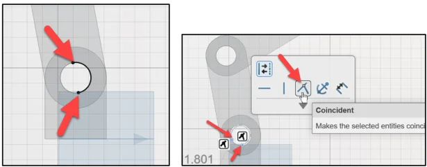
Note: With imported geometry, sometimes half of the circular edge is selected with Convert Entities. To create a closed entity, deselect Convert Entities. Drag the arc endpoints closer to each other as illustrated. Insert a Coincident constraint between the two end points of the arc.
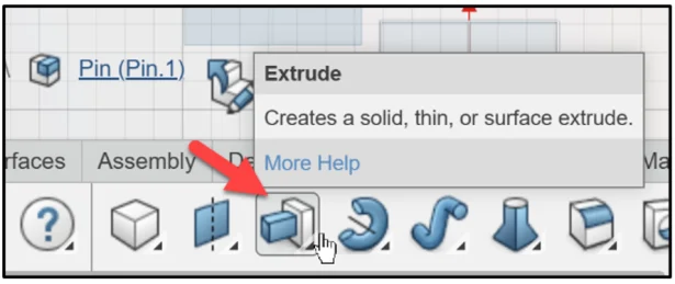
Use the Extrude tool to create the Pin. Select the Up to geometry (Up to Surface) End Condition option. Select the flat back face of component (Part.2). The selection makes the Pin exactly long enough to touch the back face of the mating component The length of the Pin is defined by the assembly, not by a static dimension.
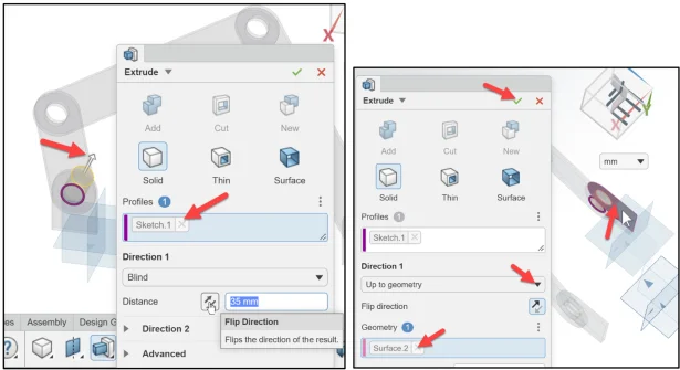
Click Extrude from the Features tab.
The Extrude dialog box is displayed. Solid is the default option. Sketch.1 is displayed in the Profiles box.
Click Flip Direction. The Extrude direction arrow points backwards.
Select Up to geometry for Direction 1.
Click the back flat face of Part.2. Surface.2 is displayed in the Geometry box.
Click OK.
Display a Trimetric view. Fit the model to the Work Area.
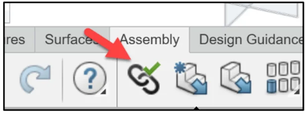
Click Solve from the Standard tab.
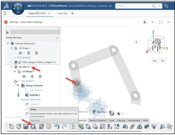
De-activate External References from the Assembly tab.
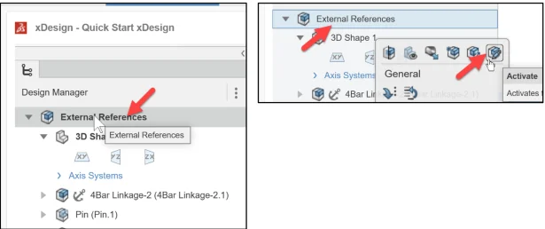
Activate the top-level of the assembly.
Double-click External References in the Design Manager as illustrated. Note: The visual changes in the Design Manager and Work Area. You can also right-click External References in the Design Manager and click Activate from the Content box.
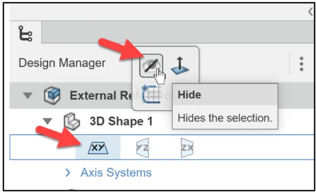
Hide all planes to improve clarity.
Insert the Long Pin.
Click Insert from the Assembly tab in the Action bar.
The Open box is displayed.
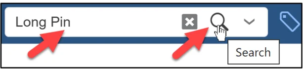
Enter Long Pin in the Search box.
Click Search.
Click inside the Long Pin box from the Results area.
Click OK.
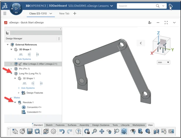
The Long Pin component is inserted to the Origin.
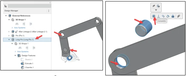
Click Long Pin (Long Pin.1) in the Design Manager. The Triad is displayed.
Use the Triad to move and rotate the Long Pin, and position it for a Concentric mate.
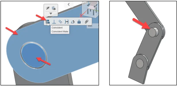
Create a Concentric mate between the outside cylindrical face of the Long Pin and the inside cylindrical face of Part 4 (Part4.1).
Create a Coincident mate between the front flat face of the Long Pin (chamfer) and the front flat face of Part 4 (Part4.1). Revolute.1 is displayed in the Mates folder.
Rotate the model and view the inserted mated Long Pin component.
Display a Trimetric view. Fit the model to the Work Area.
In the next section, apply the Copy with Mates tool. The Copy with Mates tool creates additional instances of a component (Long Pin) in the assembly. It also includes their mates from the original instance. You need not recreate the mates for each new instance. You can include or replace the existing mates with the copied component.
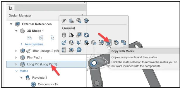
Right-click Long Pin from the Design Manager.
Click Copy with Mates from the content box.
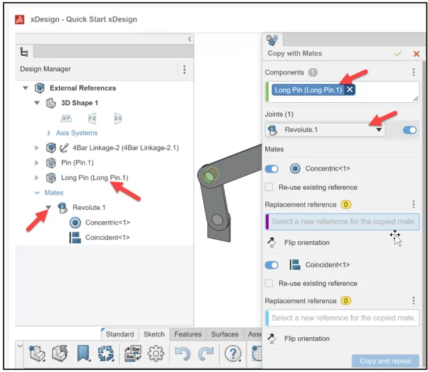
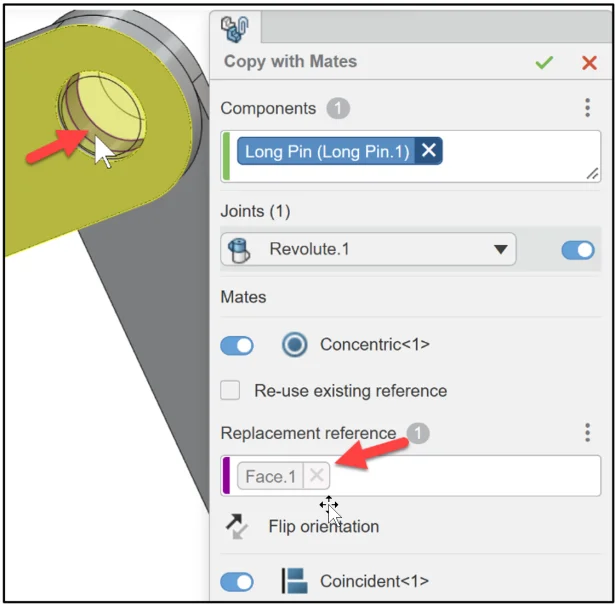
The Copy with Mates dialog box is displayed. Long Pin is displayed in the Components box. Revolute.1 is selected in the Joint box. Revolute.1 (Concentric, Coincident) was created using the Long Pin and 4Bar Linkage-2. The mates associated with Long Pin are listed in the dialog box. Note: By default, component mates are copied.
Click the inside cylindrical face of Part4 (Part4.2) as illustrated. Face.1 is displayed in the first Replacement reference box.
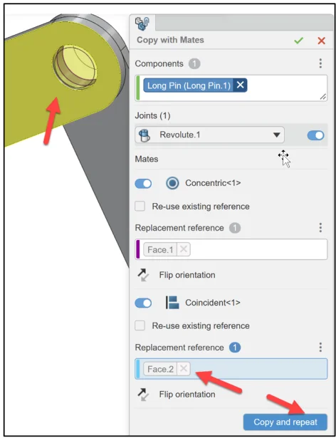
Click the front flat face of Part4 (Part4.1) as illustrated. Face.2 is displayed in the second Replacement reference box.
Click Copy and repeat. Revolute.2 (Concentric, Coincident) is created.
Zoom in on the inside cylindrical face of Part1 (Part1.2).
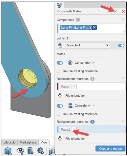
Click the inside cylindrical face of Part1 (Part1.2). Face.1 is displayed in the first Replacement reference box.

Click the front flat face of Part4 (Part4.2). Face.2 is displayed in the second Replacement reference box.
Click OK. Revolute.3 (Concentric, Coincident) is created.
Display a Trimetric view. Fit the model to the Work Area. View the results.
We are finished with the lesson.
Academic Community: After you create a 3DEXPERIENCE ID, Educators, can get more information on xDesign and SOLIDWORKS. Request to join the 3DEXPERIENCE Academic Community for free at go.3ds.com/academiccommunity.
Student Community: Students, join the student community for free at go.3ds.com/studentcommunity. Check out great posts on Mechanism Mondays, FEA Fridays, Solid Saturdays (animations), Formula Student and Formula SAE exercises.
Stay tuned for David’s next SOLIDWORKS xDesign Lesson #10: Sketching, Constraints and Dimensions
To review the previous lessons, go to:
SOLIDWORKS xDesign Lesson #1: Getting Started
SOLIDWORKS xDesign Lesson #2: Mouse Control and Collaborative Space
SOLIDWORKS xDesign Lesson #3: Sketch Planes
SOLIDWORKS xDesign Lesson #4: Create A Dashboard
SOLIDWORKS xDesign Lesson #5: Views and Orientations
SOLIDWORKS xDesign Lesson #6: Importing Files and Using Bookmarks