
After teaching 1000’s of students and writing about SOLIDWORKS for over 25 years, David Planchard, emeritus WPI, is exploring xDesign. Through the SOLIDWORKS xDesign Lesson series, David helps educators understand the differences and similarities between xDesign and SOLIDWORKS through simple examples. He also introduces new apps in the engineering design process.
Most xDesign features start with a sketch. Sketches are the foundation for creating features.
A sketch is located on a reference plane, face or a created plane.
Does it matter what plane you start the first sketch on? Yes. When you create a new component, the three default planes are aligned with specific views. The plane you select for your first sketch determines the orientation of the component. Selecting the correct plane to start your component is very important.
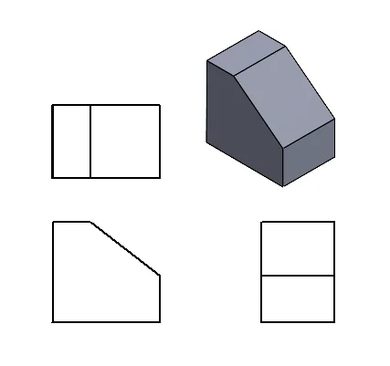
Before an object is created, examine which views will best provide the information required to manufacture the component. The surface, as you look at the component, is called the Front view.
To obtain the Front view of a component, turn the component (either physically or mentally) so that the front of the object is all you see. The Top and Right views can be obtained in a similar fashion.
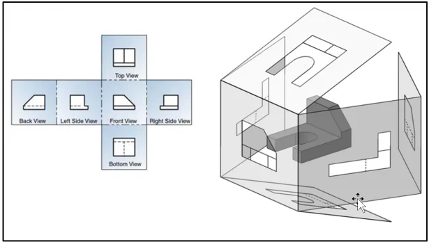
Orthographic projection provides the ability to represent the shape of the component using two or more views. These views together with dimensions and annotations are sufficient to manufacture the component.
The six principle views are Front, Top, Right, Back, Bottom, Left in Third Angle Projection.
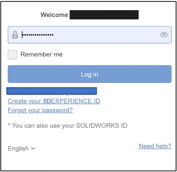
Login to the 3DEXPERIENCE platform.
Start xDesign.
Click the center of the Compass as illustrated for Roles, Apps & Solutions portfolio.
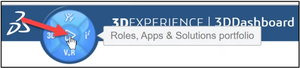
The 3DDashboard is displayed. The dashboard displays the Roles and Apps that you have assigned or purchased. Your dashboard will differ. Your administrator can create a unique dashboard in a classroom environment.
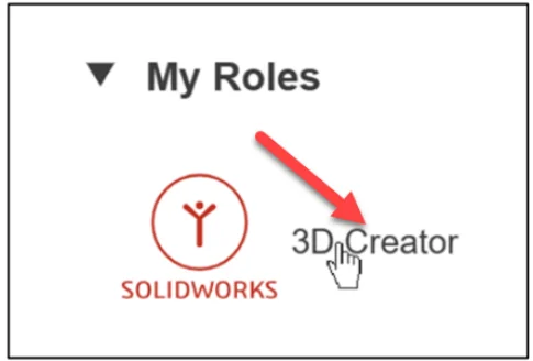
Click 3D Designer under the My Roles (xDesign). 3D Designer role is assigned to educators and students.
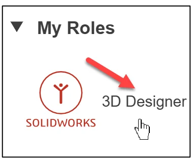
Note: 3D Creator is for commercial clients and makers.
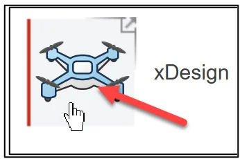
Click xDesign to launch the App. The xDesign App creates components in a single modeling environment. The term component is used because both parts and assemblies are treated the same.
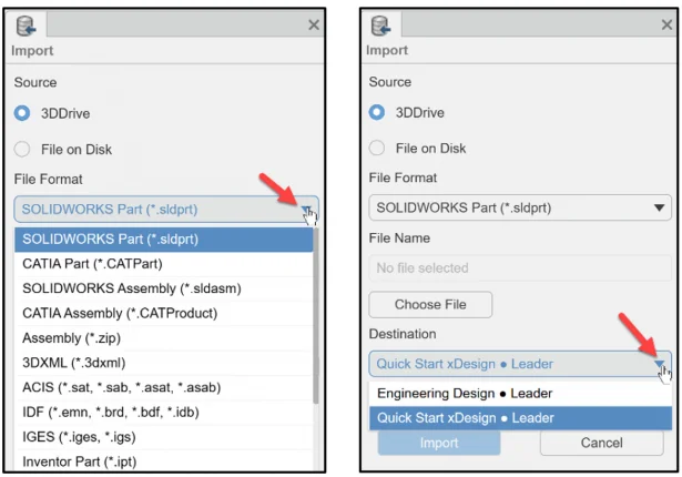
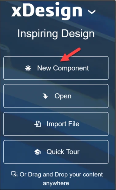
Create a new component. Note: You have the option to Import various file formats. This makes it easy to communicate and share designs with your team members, regardless of location.
Click *New Component.
The default Name* of the component is Physical Product 1.
The default Location defines the Collaborative space (cloud storage) where your components are saved. This also makes it easy to communicate and share designs with your team members, regardless of location.
The default Location maybe named: Common Space. Collaborative space location will differ depending on setup.
The 3DSpace app is used to create Collaborative space locations. I use SOLIDWORKS xDesign Collaborative space and the 3DEXPERIENCE mouse control for all lessons.
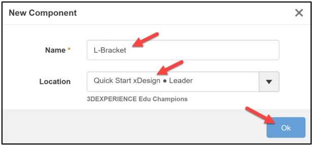
Rename the default New Component (Physical Product 1).
Enter L-Bracket for Name*.
Click OK.
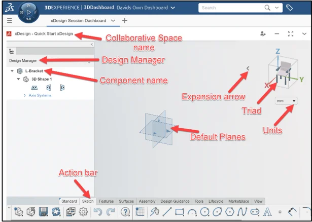
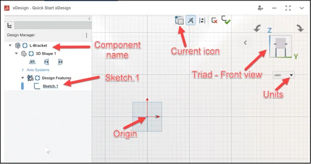
The xDesign App is displayed.
Trimetric Planes xy, yz, zx are located at the center of the Work Area.
The Planes are used for model orientation. The default axes, +x, +y, +z are in displayed with small blue arrows. Note: To change the component name, slowly double-click the name and enter a new name.
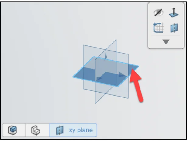
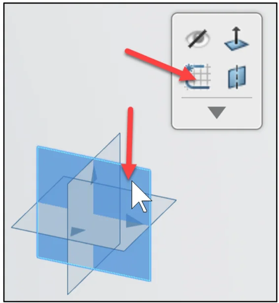
Click the xy plane (Top) in the Work Area as illustrated. The xy plane is highlighted in the Work Area and in the Design Manager. The Content toolbar is displayed.
Deactivate the Top plane.
Press the Esc key.
Click on the zx plane (Right) as illustrated. The plane is highlighted. The Content toolbar is displayed.
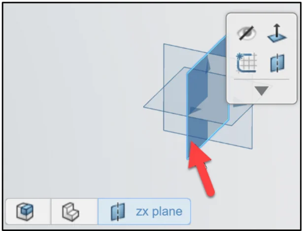
Deactivate the Right plane.
Press the Esc key.
Click on the yz plane (Front) as illustrated. The plane is highlighted.
Click Sketch from the Context toolbar.
The yz plane (Front) is displayed.
The reference Triad helps the user to view the sketch, feature and component on the selected plane or axis.
In the Work Area, the sketch options are displayed.
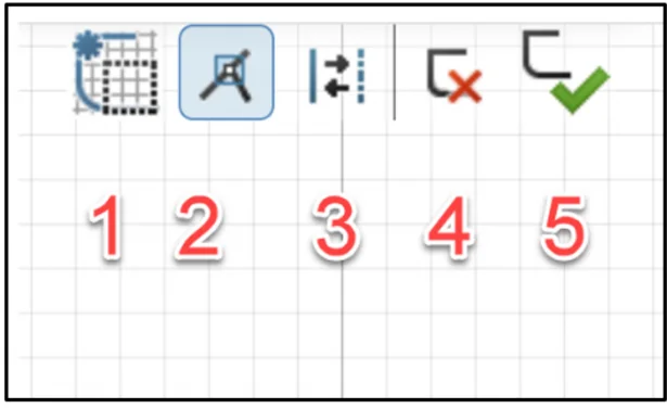
- Displays current icon and feedback.
- Switches sketch snapping and interference on or off.
- Switches between construction mode and regular sketch mode.
- Exit sketch, no sketch changes are made.
- Exit sketch to accept any sketch changes.
Create Sketch.1 of the L-Bracket. Sketch a vertical and horizontal line that intersects the Origin.
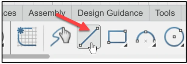
Click Line from the Sketch tab. The pointer displays the Line icon. This is similar to SOLIDWORKS.
Click a position directly above the Origin as illustrated for the first point.
Click the Origin as the second point.
Click a position directly right of the Origin as the third point.
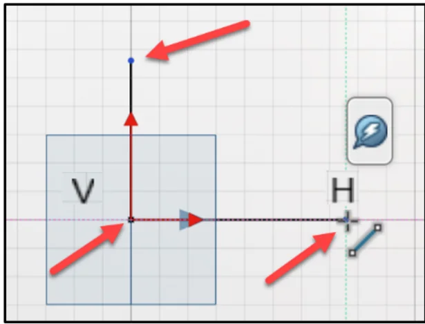
Click Line to deselect the Line entity.
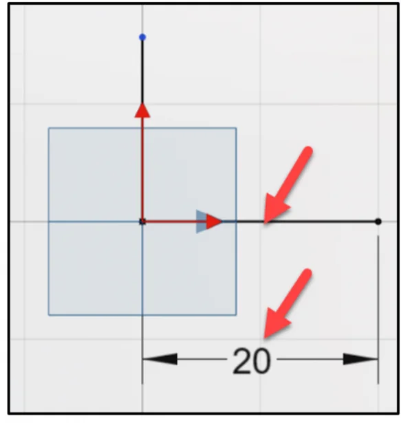
Enter the horizontal dimension.
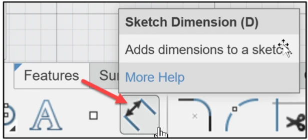
Click Sketch Dimension from the Action bar Sketch tab. This is similar to selecting the Smart Dimension Sketch tool in SOLIDWORKS.
Click the horizontal line.
Click a position below the line.
Enter 20.
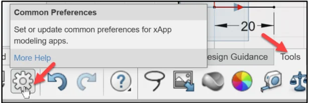
Note: Click the Tools tab from the Action bar. Click Common Preferences to address dimension decimal places.
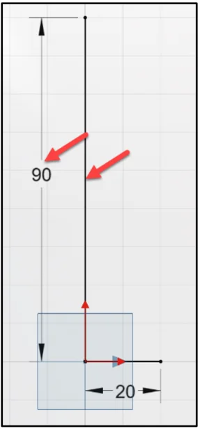
Enter the vertical dimension.
Click the vertical line.
Click a position to the left of the line.
Enter 90. Sketch.1 is fully defined and is displayed in black. Note: To edit a sketch. Click Sketch.#. Click Edit Sketch. You can also double the Sketch.#.
Press the f key to fit to the Work Area.
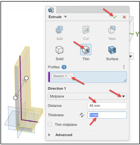
Create the Extrude-Thin feature.
Click Extrude from the Features tab.
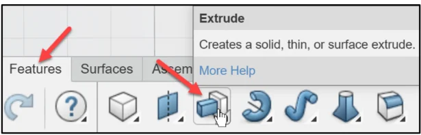
The Extrude Dialog box is displayed. Sketch.1 is displayed in the Profiles selection box.
An error is displayed. Click Close.
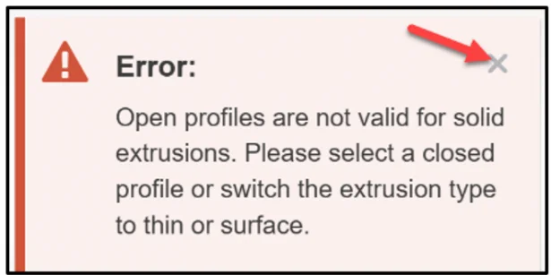
Select Thin for Extrude type.
Select Midplane for Direction 1.
Enter 45 for Distance.
Enter 5 for Thickness.
Click OK (green checkmark) to complete the task.
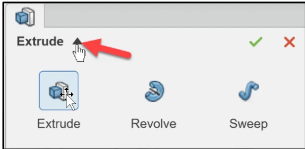
Note: xDesign offers various Super Features for Sketch-based Features as illustrated.
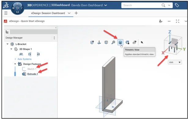
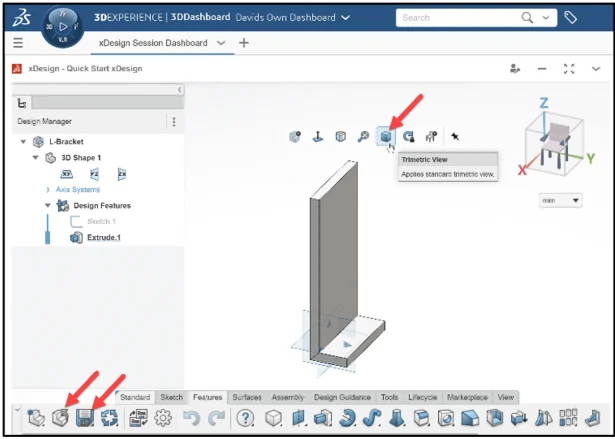
Display a Trimetric view in the Work Area.
Click Trimetric View from the Expansion arrow in the Work Area. Note: Double-click Extrude.1 in the Design Manager to edit the feature.
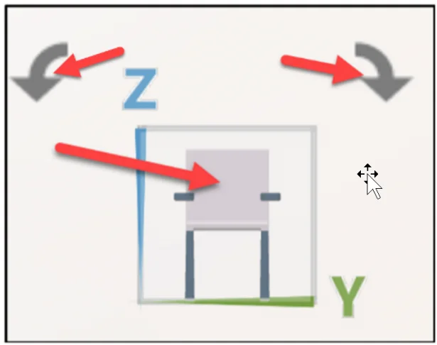
Explore the Triad in xDesign.
Click the X label from the Triad as illustrated.
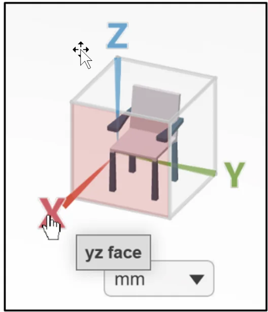
The yz face is displayed.
The L-Bracket component is displayed normal to the yz plane (Front).
The rotate arrow in the Triad, spins the model clockwise or counter clockwise 90 degrees.
Return to the Trimetric view.
Click Trimetric View from the Expansion arrow in the Work Area
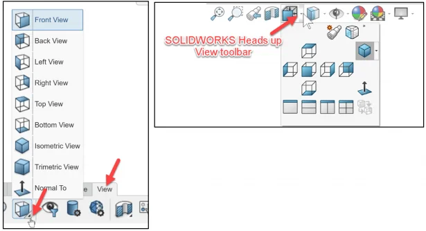
Note: View additional views. Click the View tab in the Action bar. Click the expand arrow in the Trimetric view icon. This option is similar to the SOLIDWORKS Heads up View toolbar.
Save and Close the L-Bracket component.
Clcik Save from the Action bar.
Click Close from the Action bar.
Learn more about SOLIDWORKS xDesign and the 3DEXPERIENCE Platform.
Academic Community: After you create a 3DEXPERIENCE ID, Educators, can get more information on xDesign and SOLIDWORKS. Request to join the 3DEXPERIENCE Academic Community for free at go.3ds.com/academiccommunity.
Student Community: Students, join the student community for free at go.3ds.com/studentcommunity. Check out great posts on Mechanism Mondays, Heritage Tuesdays, FEA Fridays, and Solid Saturdays (animations).
Stay tuned for David’s next SOLIDWORKS xDesign Lesson #6: Importing Files and Using Bookmarks.
To review the previous lessons, go to:
SOLIDWORKS xDesign Lesson #1: Getting Started
SOLIDWORKS xDesign Lesson #2: Mouse Control and Collaborative Space
SOLIDWORKS xDesign Lesson #3: Sketch Planes
SOLIDWORKS xDesign Lesson #4: Create A Dashboard
Design well, Marie