
After teaching 1000’s of students and writing about SOLIDWORKS for over 25 years, David Planchard, emeritus WPI, is exploring xDesign. Through the SOLIDWORKS xDesign Lesson series, David helps educators understand the differences and similarities between xDesign and SOLIDWORKS through simple examples. He also introduces new apps in the engineering design process.
Most xDesign features start with a sketch. Sketches are the foundation for creating features.
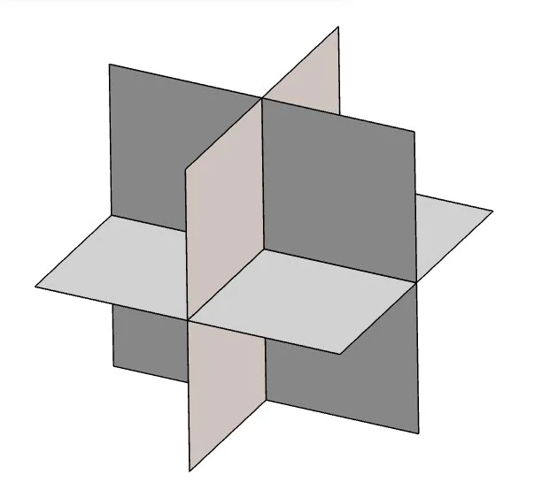
A sketch is located on a reference plane, face or a created plane.
Does it matter what plane you start the first sketch on? Yes. When you create a new component, the three default planes are aligned with specific views. The plane you select for your first sketch determines the orientation of the component. Selecting the correct plane to start your component is very important.
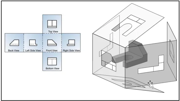
Before an object is created, examine which views will best provide the information required to manufacture the component. The surface, as you look at the component, is called the Front view.
To obtain the Front view of a component, turn the component (either physically or mentally) so that the front of the object is all you see. The Top and Right views can be obtained in a similar fashion.
Orthographic projection provides the ability to represent the shape of the component using two or more views. These views together with dimensions and annotations are sufficient to manufacture the component.
The six principle views are Front, Top, Right, Back, Bottom, Left in Third Angle Projection.
Use your unique link to the 3DEXPERIENCE platform.
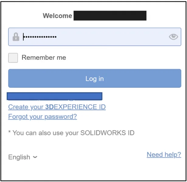
Login to the 3DEXPERIENCE platform.
Start xDesign.
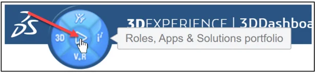
Click the center of the Compass as illustrated for Roles, Apps & Solutions portfolio.
The 3DDashboard is displayed. The dashboard displays the Roles and Apps that you have assigned or purchased. Your dashboard may differ. Your administrator or instructor can create a unique dashboard in a classroom environment.
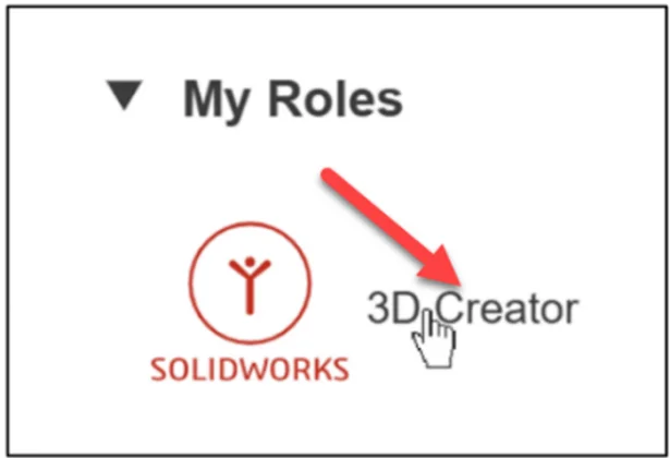
Click 3D Designer under the My Roles (xDesign). 3D Designer role is assigned to educators and students.
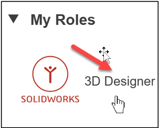
Note: 3D Creator is for commercial clients and makers.
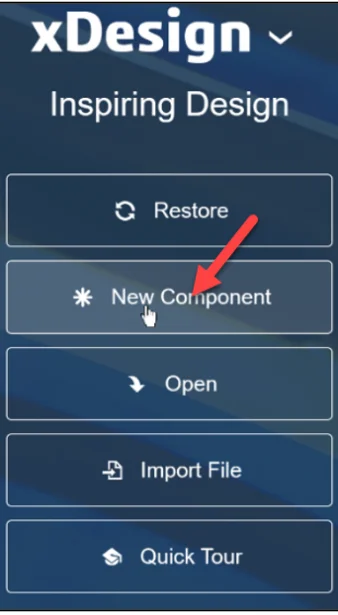
Click xDesign to launch the App. The xDesign App creates prismatic parts and assemblies.
Create a new component. Note: You may see the Restore option if you timed out or your internet connection was interrupted
Click *New Component.
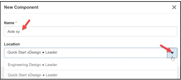
The default Name* of the component is Physical Product 1.
The default Location defines the Collaborative space (cloud storage) where your components are saved. This also makes it easy to communicate and share designs with your team members, regardless of location.
The default Location maybe named: Common Space. Collaborative space location will differ depending on setup.
The 3DSpace app is used to create Collaborative space locations.
As an example, I created two Collaborative space locations as displayed in the New Component box: Engineering Design and Quick Start xDesign. I use the Quick Start xDesign Collaborative space for all lessons.
Enter Axle xy for Name*.
Click OK.
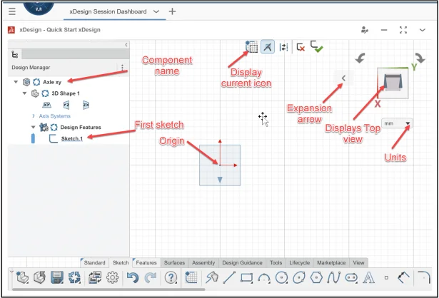
The xDesign App is displayed. Quick Start xDesign is the Collaborative space location.
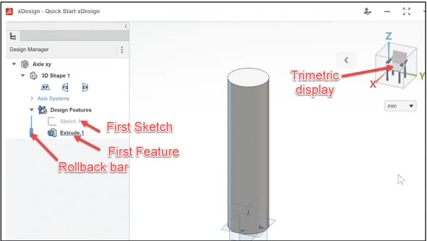
The Design Manager display is similar to the SOLIDWORKS FeatureManager. They both provide information about the Physical Product (Axle xy). The 3D Shape 1 contains geometry, sketches, and features.
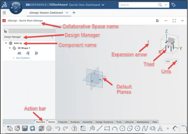
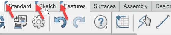
The Action bar contains design tools similar to the SOLIDWORKS CommandManager with various default tabs.
Note: Double-click a tab to lock the tools to the Action bar (arrow). Double-click again to unlock the tab tools.
The default reference planes are: xy (Top), yz (Front), and zx (Right).
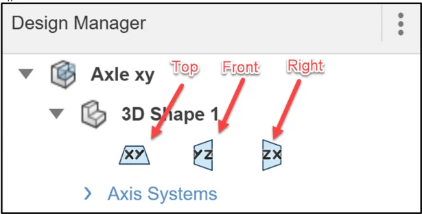
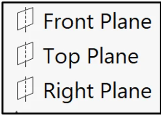
SOLIDWORKS uses Front, Top and Right Planes for Third Angle projection.
Create Sketch.1 on the xy (Top) plane.
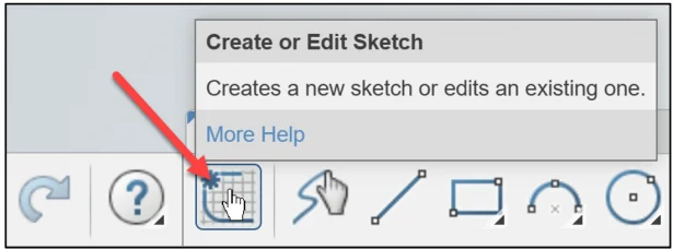
Click Create or Edit Sketch from the Action bar.
Click xy (Top) plane in the Design Manager.
The xy plane is displayed normal in the Work Area. View the Work Area.
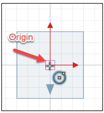
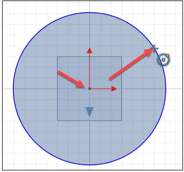
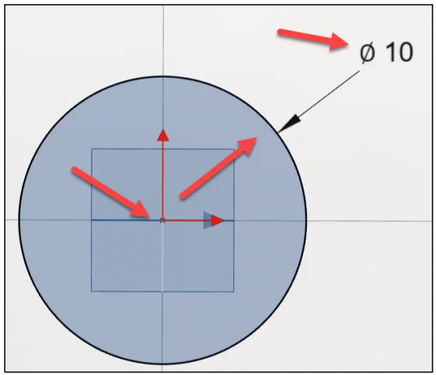
Create a circle centered about the Origin. The Origin is the intersection of the x, y, z planes.
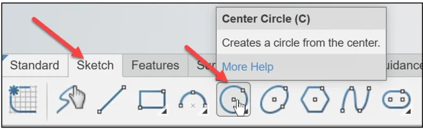
Click Center Circle from the Sketch tab. The Sketch entities in xDesign are similar to the ones in SOLIDWORKS.
Click the Origin in the Work Area. Note the feedback symbol. This is the first point of the circle. It is very important that you always reference the sketch to the Origin. This helps to fully define the sketch.
Click a position to the right as illustrated. Note the Circle icon. This is similar to SOLIDWORKS.
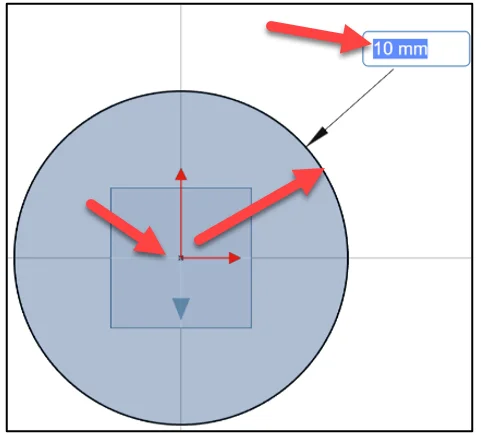
Dimension the circle. The default units are in Millimeters.
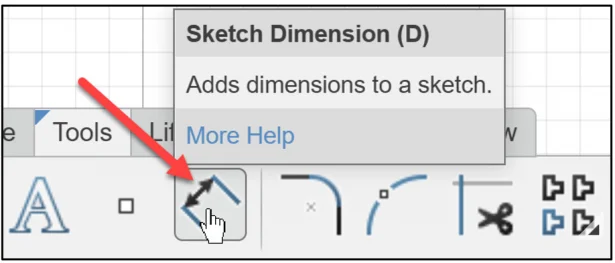
Click the Sketch Dimension entity. This Sketch Dimension entity is similar to the Smart Dimension Sketch tool in SOLIDWORKS.
Click the diameter of the circle.
Click a position to place the dimension.
Enter 10.
Sketch.1 is fully defined in the Design Manager. The fully defined sketch symbol is similar to SOLIDWORKS.
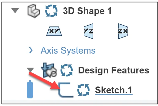
Fully defined sketches are required to manufacture the component. It is considered poor design practice not to fully define a sketch. You will be tempted in order to save design time, but keep in mind that the extra couple of minutes you take to do something right the first time will save you additional time in the end.
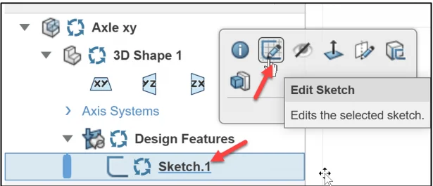
Note: To edit a sketch. Click the Sketch.#. Click Edit Sketch.
Features are geometry building blocks.
Features add or remove material.
Features are created from sketched profiles or from edges and faces of existing geometry.
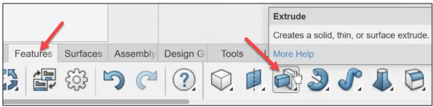
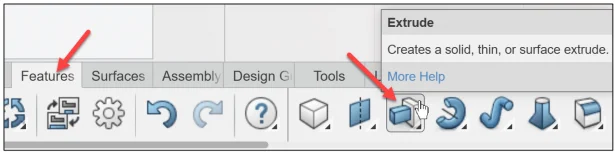
Create an Extrude feature. An Extrude is a sketch base feature. The Extrude feature adds material to the component. An extrusion extends a profile along a path normal to the profile plane for a specified distance. The movement along that path becomes the solid 3D model.
Click the Extrude feature from the Features tab in the Action bar.The feature icons are similar to SOLIDWORKS.
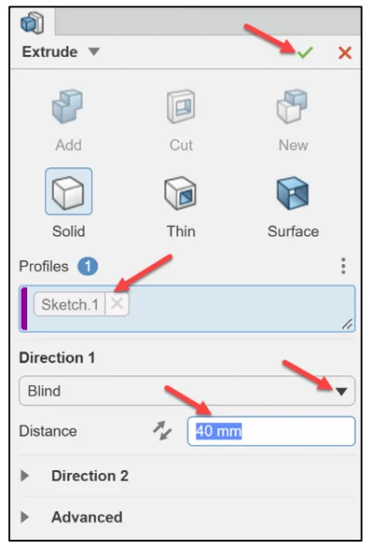
The Extrude Dialog box is displayed. In SOLIDWORKS this is called the Extrude PropertyManager.
Sketch.1 is displayed in the Profiles selection box.
Select Blind for Direction 1 from the drop-down menu. This is similar in SOLIDWORKS to select an End Condition.
Enter 40 for Distance.
Click OK (green checkmark) to complete the command.
Fit the model to the Work Area. Display a Trimetric view.
Press the f key to fit the model to the Work Area. This is a similar in SOLIDWORKS.
Click the Expansion arrow in the Work Area.
Click Trimetric view.
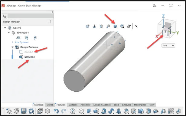
The standard view in xDesign is Trimetric. This is similar to SOLIDWORKS. A Trimetric view is created using 3 axes where each of the angles between them is different (there are no equal angles).
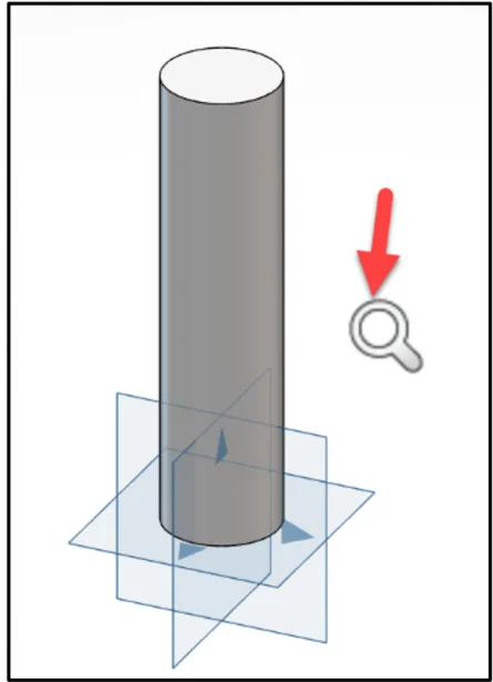
Note: I use the 3DEXPERIENCE mouse control in all lessons. Use the middle mouse wheel to Zoom In/Out in the Work Area. You can also use the right mouse button. SOLIDWORKS uses a similar Zoom icon.
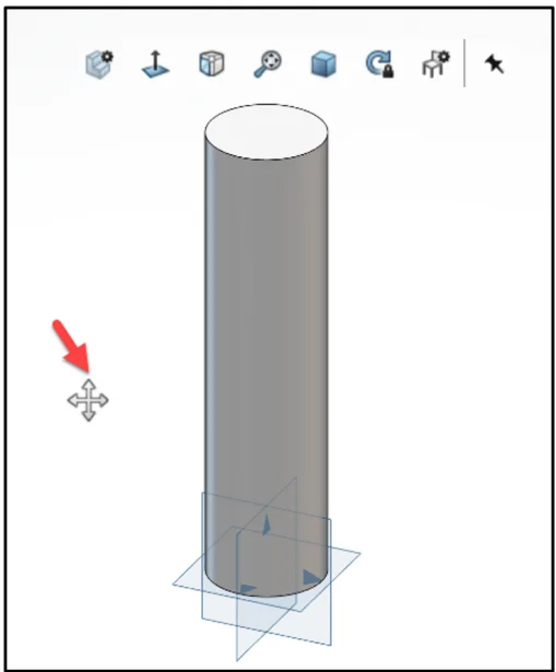
Note: Hold the middle mouse button down, drag the component in the Work Area. The pan icon is displayed. SOLIDWORKS uses a similar pan icon.
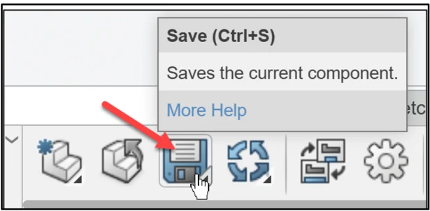
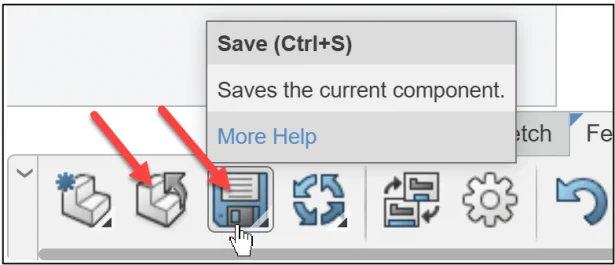
Save the component.
Click Save from the Action bar.
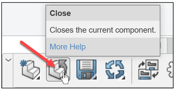
Close the Axle xy component.
Click Close from the Action bar.
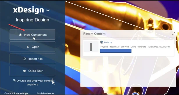
Create a new component. Note: You have the option to Open an existing component in your Collaborative space where your components are saved.
Click *New Component. Note: The Recent Content box.
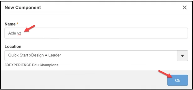
Rename the default New Component (Physical Product 1). I use the Quick Start xDesign Collaborative space for all lessons.
Enter Axle yz for Name*.
Click OK.
The xDesign App is displayed.
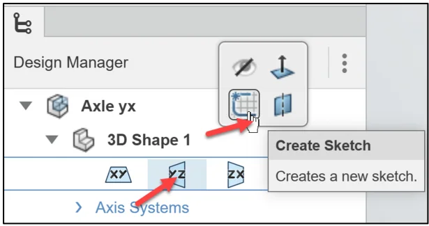
Create Sketch.1 on the yz (Front) plane.
Click yz (Front) plane in the Design Manager. Note: To deselect the yz (Front) plane, click inside the Work Area.
Click Create Sketch from the Context toolbar. There are multiple ways to create sketches and features.
The yz plane is displayed normal in the Work Area. The Triad displays a front view.
Sketch a 10mm circle centered about the Origin. This process is similar in SOLIDWORKS.
Create an Extrude feature.
Click the Extrude feature from the Features tab in the Action bar.
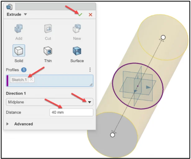
The Extrude Dialog box is displayed.
Sketch.1 is displayed in the Profiles selection box.
Select Midplane from the drop-down menu for Direction 1. The feature is centered about the yz plane.
Enter 40 for Distance.
Click OK (green checkmark) to complete the command. View the Work Area.
Click the Expansion arrow in the Work Area.
Click Trimetric view.
Press the f key to fit the model to the Work Area.
Save the component.
Click Save from the Action bar.
Close the Axle yz component.
Click Close from the Action bar.
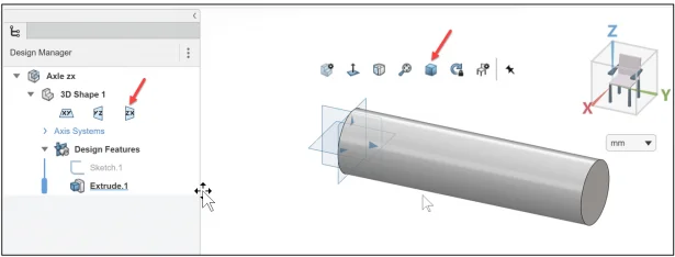
The final view of Axle zx is displayed below in a Trimetric view.
Academic Community: After you create a 3DEXPERIENCE ID, Educators, can get more information on xDesign and SOLIDWORKS. Request to join the 3DEXPERIENCE Academic Community for free at go.3ds.com/academiccommunity.
Student Community: Students, join the student community for free at go.3ds.com/studentcommunity. Check out great posts on Mechanism Mondays, Heritage Tuesdays, FEA Fridays, and Solid Saturdays (animations).
Stay tuned for David’s next SOLIDWORKS xDesign Lesson #4: Dashboards.
To review the previous lessons, go to:
SOLIDWORKS xDesign Lesson #1: Getting Started
SOLIDWORKS xDesign Lesson #2: Mouse Control and Collaborative Space
Design well, Marie