
After teaching 1000’s of students and writing about SOLIDWORKS for over 25 years, David Planchard, emeritus WPI, is exploring xDesign. Through the SOLIDWORKS xDesign Lesson series, David helps educators understand the differences and similarities between xDesign and SOLIDWORKS through simple examples. He also introduces new apps in the engineering design process.
SOLIDWORKS xDesign (cloud) versus SOLIDWORKS (desktop)
Create assemblies using the Bottom-up design approach, the Top-down design approach, or a combination of both methods. SOLIDWORKS uses both Bottom-up and Top-down design approaches. In the Top-down approach, when you create a part In-context, the part is virtual. The virtual part does not exist outside of the assembly.
xDesign is based on a systems engineering approach (single modeling environment) which is Top-down. The Physical Products (components) can be used between many apps on the 3DEXPERIENCE platform. In xDesign, the term component is used because both parts and assemblies are treated the same.
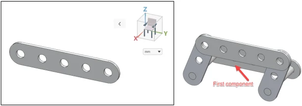
In this lesson, import three SOLIDWORKS parts into a Collaborative space. Create a ROCKER component. Insert the SOLIDWORKS parts, one at a time. The first component is inserted to the Origin and is fixed. All other components are inserted to the Origin and are not fixed.
The three default planes in xDesign are: xy (Top), yz (Front), and zx (Right). The three default planes in SOLIDWORKS are: Front, Top, and Right. This is a very important difference between SOLIDWORKS and xDesign when you insert a SOLIDWORKS part into xDesign. The orientation will be different.
Start xDesign and Create a New Component, ROCKER
Login to the 3DEXPERIENCE platform.
Start xDesign.
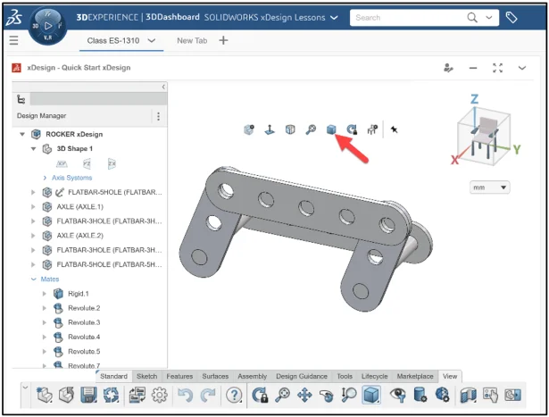
Click xDesign to launch the App or open an existing Dashboard with xDesign as a Widget. xDesign has a single modeling environment. The term component is used because both parts and assemblies are treated the same.
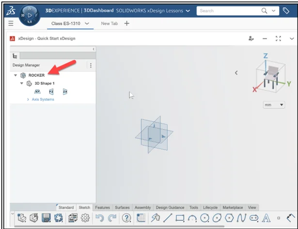
Create a New Component.
Name the New Component ROCKER.
Download, Extract and Import
Click the Rocker to download the needed components. Extract three SOLIDWORKS files. Import the three SOLIDWORKS files: (AXLE, FLATBAR-3 HOLE, and FLATBAR-5 HOLE) into your xDesign Collaborative space.
Note: A Windows model file cannot be directly opened in xDesign. The model file needs to be imported and saved to a collaborative space.
In this lesson, my collaborative space is named Quick Start xDesign. I created a Tab in my dashboard for an xDesign class, named ED-1310.
The default units are mm.
Insert the Components and Mate Components
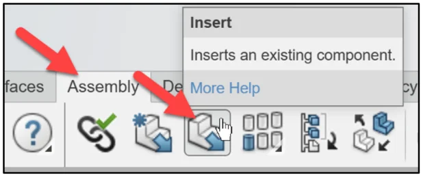
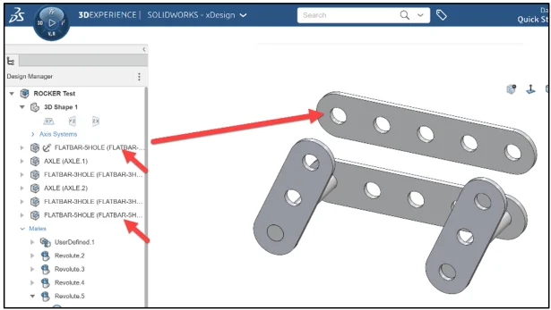
Insert the first component, FLATBAR-5 HOLE.
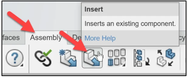
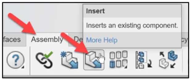
Click Insert from the Assembly tab in the Action bar.
The Open box is displayed. Use Search and the 6W tags to find the imported SOLIDWORKS parts.
In xDesign, you cannot open files using the standard Windows open dialog. Search for components as you would using Google. Search for the FLATBAR-5 HOLE part.
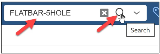
Enter FLATBAR-5HOLE in the Search box.
Click Search.
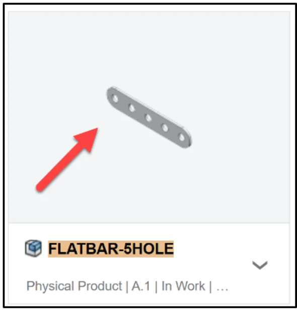
Click inside the FLATBAR-5HOLE box from the Results area.
Click OK.
The FLATBAR-5HOLE component is inserted to the Origin. The first component is fixed aligned to the three default planes in xDesign. The FLATBAR-5HOLE component is 90 degrees from the required orientation.
Hide Planes
Hide the default planes to improve clarity.
Click xy in the Design Manager. Click Hide from the Content bar.
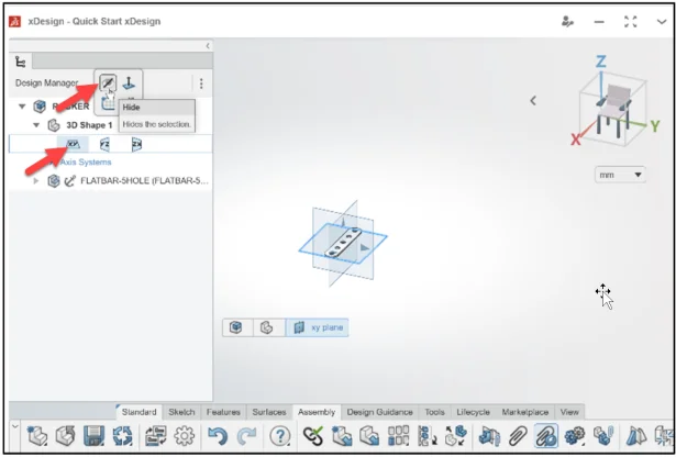
Repeat the hide process for the yz plane and zx plane.
Fit the component to the Work Area.
Press the f key.
Fix Component and Float Component
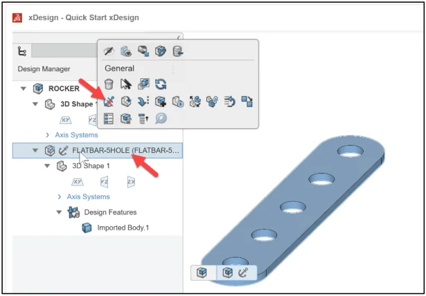
The FLATBAR-5HOLE component is located at the Origin. It is not in the required orientation. Address the orientation using three mates.
Right-click FLATBAR-5HOLE in the Design Manager.
Click Float Component from the General Content box.
Coincident Mate and Perpendicular Mates
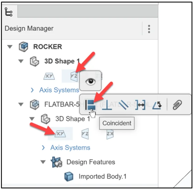
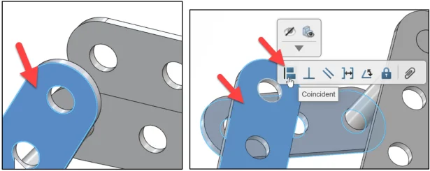
Insert the first mate. Insert a Coincident mate between the yz plane of the ROCKER and the xy plane of the FLATBAR-5HOLE component.
Click the yz plane of the ROCKER. Hold the Ctrl key down. Click the xy plane of the FLATBAR-5HOLE component. Release the Ctrl key. The pop-up menu is displayed. Click Coincident. The Mate folder is added to the Design Manager. Coincident<1> is created.
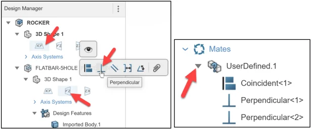
Insert the second mate. Insert a Perpendicular mate between the xy plane of the ROCKER and the yz plane of the FLATBAR-5HOLE component.
Click the xy plane of the ROCKER. Hold the Ctrl key down. Click the yz plane of the FLATBAR-5HOLE component. Release the Ctrl key. The pop-up menu is displayed. Click Perpendicular. Perpendicular<1> is created in the Mates folder.
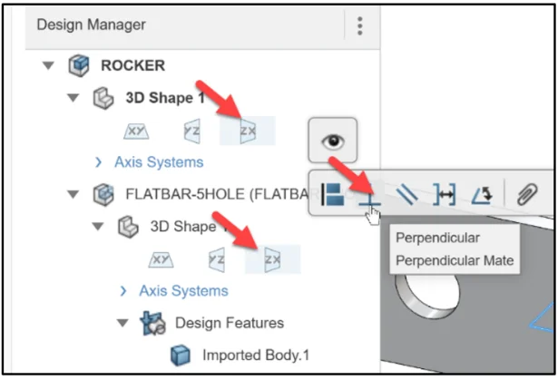
Insert the third mate to address the final orientation. Insert a Perpendicular mate between the zx plane of the ROCKER and the zx plane of the FLATBAR-5HOLE component.
Click the zx plane of the ROCKER. Hold the Ctrl key down. Click the zx plane of the FLATBAR-5HOLE component. Release the Ctrl key. The pop-up menu is displayed. Click Perpendicular. Perpendicular<2> is created in the Mates folder.
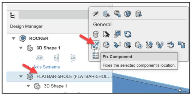
Fix the FLATBAR-5HOLE component to the Origin.
Right-click FLATBAR-5HOLE from the Design Manager.
Click Fix Component from the Content box.
Note: Remember the assembly that you are creating and the location of the components.
Search, Insert, Move and Mate the AXLE
Insert the second component, AXLE.
Click Insert from the Assembly tab in the Action bar.
The Open box is displayed. Search for AXLE.
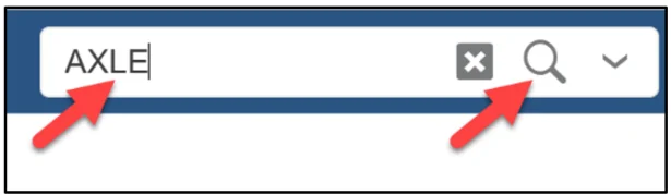
Enter AXLE in the Search box.
Click Search.
Click inside the AXLE box from the Results area.
Click OK.
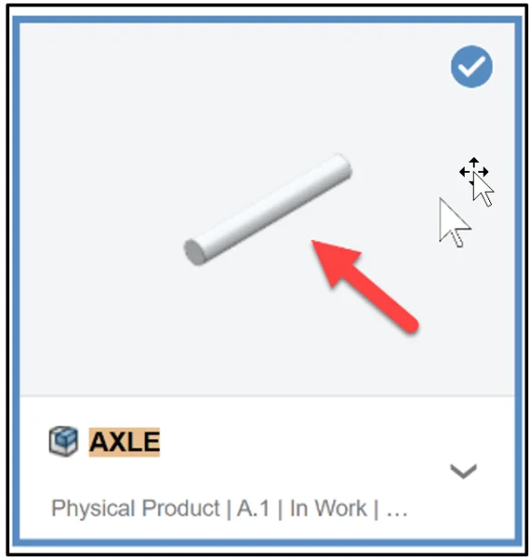
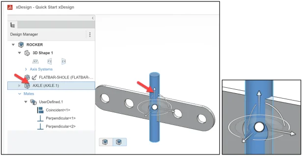
The AXLE component is inserted to the Origin. This is not the case in SOLIDWORKS. Look at the Origin first to locate components when creating mates. The AXLE is not fixed. The AXLE has the ability to move relative to the FLATBAR-5HOLE.
Display the Triad of the AXLE.
Click AXLE from the Design Manager. A Triad is displayed on the AXLE in the Work Area. Use the Triad’s direction arrows to move the component linearly and the small and large arcs to rotate the component. Note: It is a good practice to move and rotate components into their rough position first before adding mates.
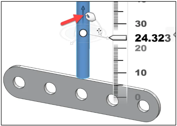
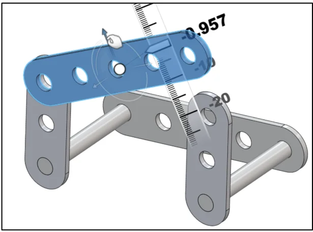
Move the AXLE upwards.
Click and drag the vertical arrow of the Triad upwards.
View the Triad ruler. Note: The hand icon.
Click a position in the Work Area.
Display the Triad of the AXLE.
Click AXLE from the Design Manager. A Triad is displayed on the AXLE.
Use the Triad to position the AXLE. Click the small arc of the Triad. Rotate the AXLE for the first Concentric mate to the FLATBAR-5HOLE. Take your time to zoom in/out and fit the components to the Work Area. This will help to select the correct faces and edges for the mating process.
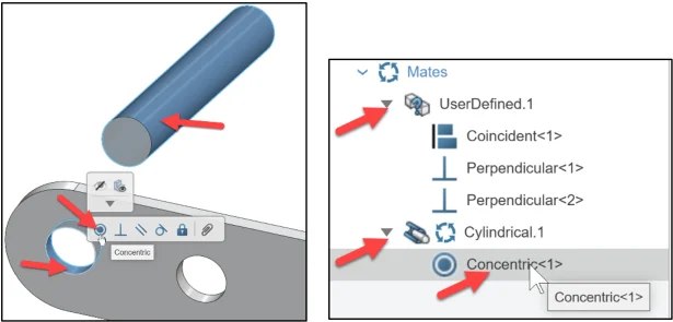
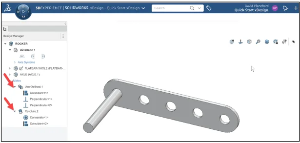
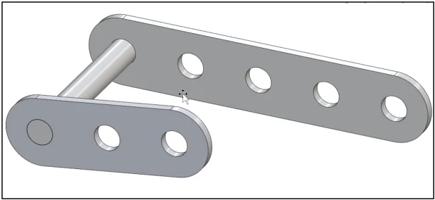
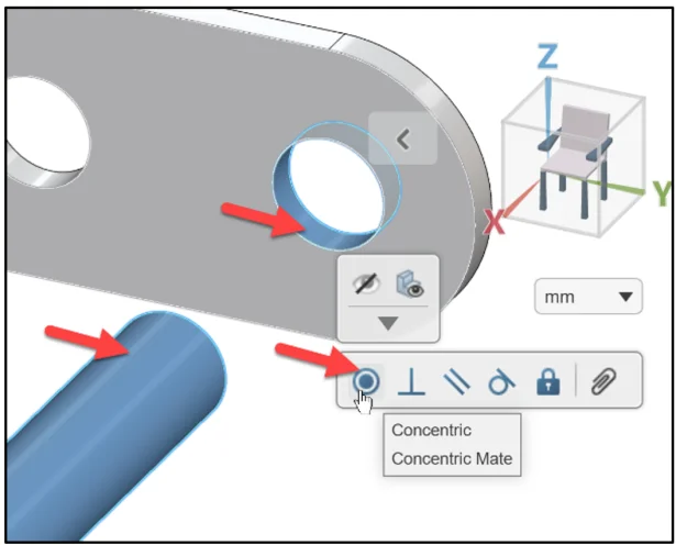
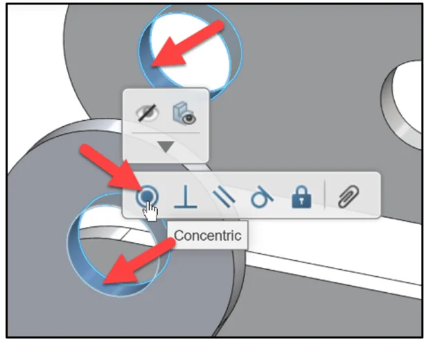
Insert a Concentric mate between the outside cylindrical face of the AXLE and the first inside hole face of the FLATBAR-5HOLE. Note: With imported geometric, sometimes half of the cylindrical face is selected.
Click the outside cylindrical face of the AXLE. Hold the Ctrl key down. Click the first inside hole face of the FLATBAR-5HOLE. Release the Ctrl key. Click Concentric from the pop-up menu. Concentric<1> is created and displayed in the Mate folder.
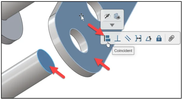
Insert a Coincident mate between the flat face of the AXLE and the flat back face of the FLATBAR-5HOLE.
Click the flat circular face of the AXLE. Hold the Ctrl key down. Click the flat back face of the FLATBAR-5HOLE. Release the Ctrl key. Click Coincident from the pop-up menu. Coincident<1> is created and displayed in the Mate folder.
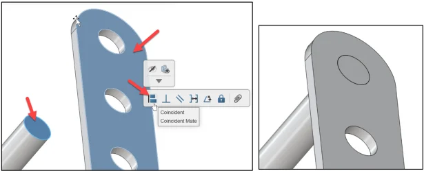
Display a Trimetric view. View the results in the Work Area.
Search, Insert, Move and Mate the FLATBAR-3HOLE
Insert the third component, FLATBAR-3HOLE.
Click Insert from the Assembly tab in the Action bar.
The Open box is displayed. Search for FLATBAR-3HOLE.
Enter FLATBAR-3HOLE in the Search box.
Click Search.
Click inside the FLATBAR-3HOLE box from the Results area.
Click OK.
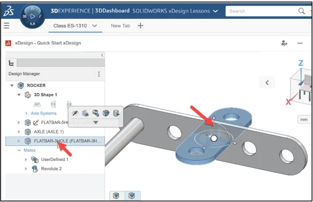
The FLATBAR-3HOLE component is inserted to the Origin. The FLATBAR-3HOLE is not fixed. The FLATBAR-3HOLEhas the ability to move and rotate relative to the FLATBAR-5HOLE.
Display the Triad of the FLATBAR-3HOLE component.
Click FLATBAR-3HOLE from the Design Manager. A Triad is displayed on the FLATBAR-3HOLE. Use the Triad’s direction arrows to move the component linearly and the small and large arcs to rotate the component.
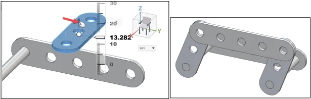
Click and drag the vertical arrow of the Triad upwards. View the Triad ruler.
Click a position in the Work Area. Note: Remember the assembly that you are creating and the location of the components.
Display the Triad of the FLATBAR-3HOLE component.
Click FLATBAR-3HOLE from the Design Manager. The Triad is displayed on the FLATBAR-3HOLE component.
Rotate the FLATBAR-3HOLEcomponent for a Concentric mate to the AXLE.
There are various ways to create mates. For the next mate, use the Mate command from the Assembly tab in the Task bar.
Insert a Concentric mate between the outside cylindrical face of the AXLE and the first inside hole face of the FLATBAR-3HOLE.
Click Mate from the Assembly tab Task bar.
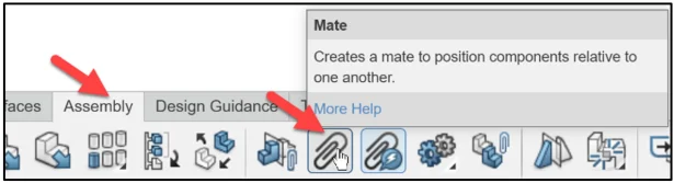
The Mate dialog box is displayed.
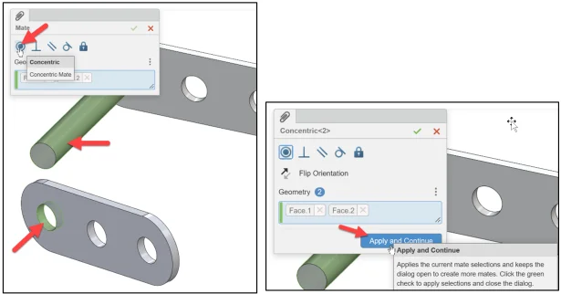
Click the outside cylindrical face of the AXLE. Face.1 is displayed in the Geometry box.
Click the first inside hole face of the FLATBAR-3HOLE. Face.2 is displayed in the Geometry box.
Click Concentric.
Click Apply and Continue.
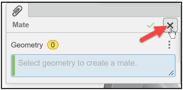
Close the Mate dialog box.
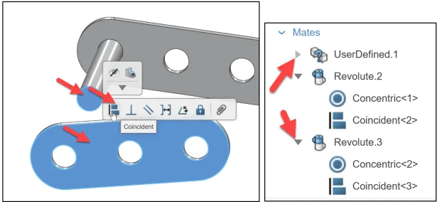
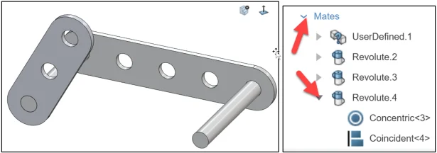
Insert a Coincident mate between the flat face of the AXLE and the flat front face of the FLATBAR-3HOLE.
Click the flat circular face of the AXLE. Hold the Ctrl key down.
Click the flat front face of the FLATBAR-3HOLE. Release the Ctrl key.
Click Coincident from the pop-up menu. Coincident is created and displayed in the Mate folder. A Revolute joint is created.
Display a Trimetric view.
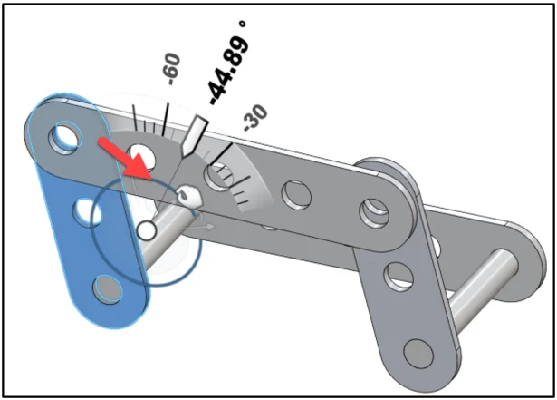
Click FLATBAR-3HOLEfrom the Design Manager. The Triad is displayed on the FLATBAR-3HOLE component.
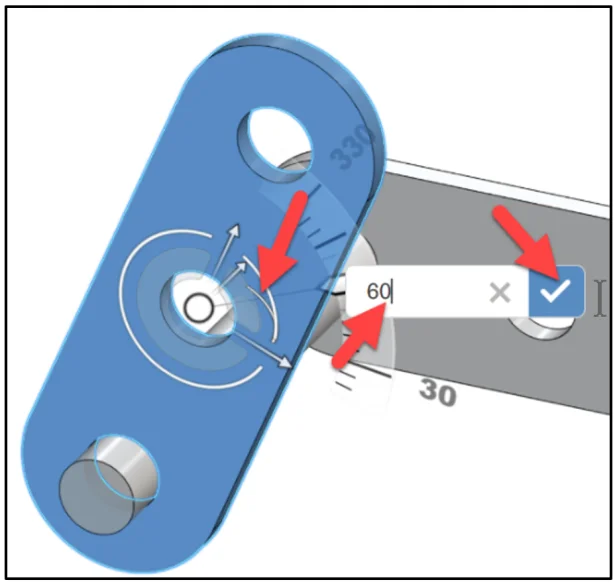
Rotate the component as illustrated using the Triad’s angle ruler, approximately 60 degrees. Click a position. Remember the assembly that you are creating and the location of the components.
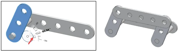
Note: Click the large outside arc of the Triad. Input the exact angle.
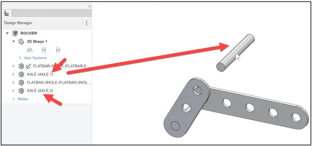
Copy the AXLE Component from the Design Manager and Mate
Insert the second AXLE component.
Click AXLE from the Design Manager. Hold the Ctrl key down. Drag AXLE into the Work Area. Release the Ctrl key. Release the mouse button. AXLE.2 is displayed.
Display the Triad of the AXLE.
Click AXLE from the Design Manager. A Triad is displayed on the AXLE. Use the Triad to position the AXLE.
Insert a Concentric mate between AXLE and the FLATBAR-5HOLE.
Click the outside cylindrical face of the AXLE. Hold the Ctrl key down. Click the last inside hole face of the FLATBAR-5HOLE. Release the Ctrl key. Click Concentric from the pop-up menu. Concentric<1> is created and displayed in the Mate folder.
Display the Triad of the AXLE.
Click AXLE from the Design Manager. A Triad is displayed on the AXLE. Use the Triad to position the AXLE.
Insert a Coincident mate between the flat circular face of the AXLE and the back face of the FLATBAR-5HOLE.
Display a Trimetric view. Review the results.
Insert and Mate the Remaining Components
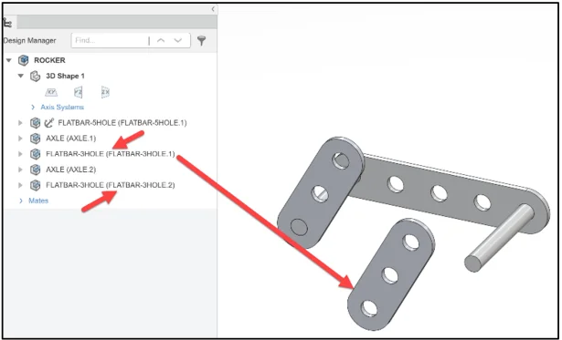
Insert the second FLATBAR-3HOLE component.
Click FLATBAR-3HOLE from the Design Manager. Hold the Ctrl key down. Drag FLATBAR-3HOLE into the Work Area. Release the Ctrl key. Release the mouse button. FLATBAR-3HOLE.2 is displayed.
Repeat the procedures in the lesson to insert a Concentric mate between the outside cylindrical face of the AXLE and the first inside hole face of the FLATBAR-3HOLE.
Repeat the procedures in the lesson to insert a Coincident mate between the flat circular face of the AXLE and the flat front face of the FLATBAR-3HOLE.
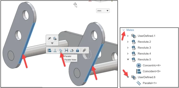
Insert a Parallel mate between the two FLATBAR-3HOLE components as illustrated.
Insert the second FLATBAR-5HOLE component.
Click FLATBAR-5HOLE from the Design Manager. Hold the Ctrl key down. Drag FLATBAR-5HOLE into the Work Area. Release the Ctrl key. Release the mouse button. FLATBAR-5HOLE.2 is displayed.
Insert a Concentric mate between the top inside hole face of the FLATBAR-3HOLE and the first inside hole face of the FLATBAR-5HOLE.
Insert a Coincident mate between the front face of the FLATBAR-3HOLE and the back face of the FLATBAR-5HOLE.
Click the front face of theFLATBAR-3HOLE component.
Rotate the FLATBAR-5HOLE to view the back face.
Hold the Ctrl key down.
Click the back face. Release the Ctrl key.
Click Coincident from the pop-up menu.
Move the second FLATBAR-5HOLE upward to insert the second Concentric and Coincident mate.
Insert the second Concentric and Coincident mate between the FLATBAR-5HOLE and the FLATBAR-3HOLE.
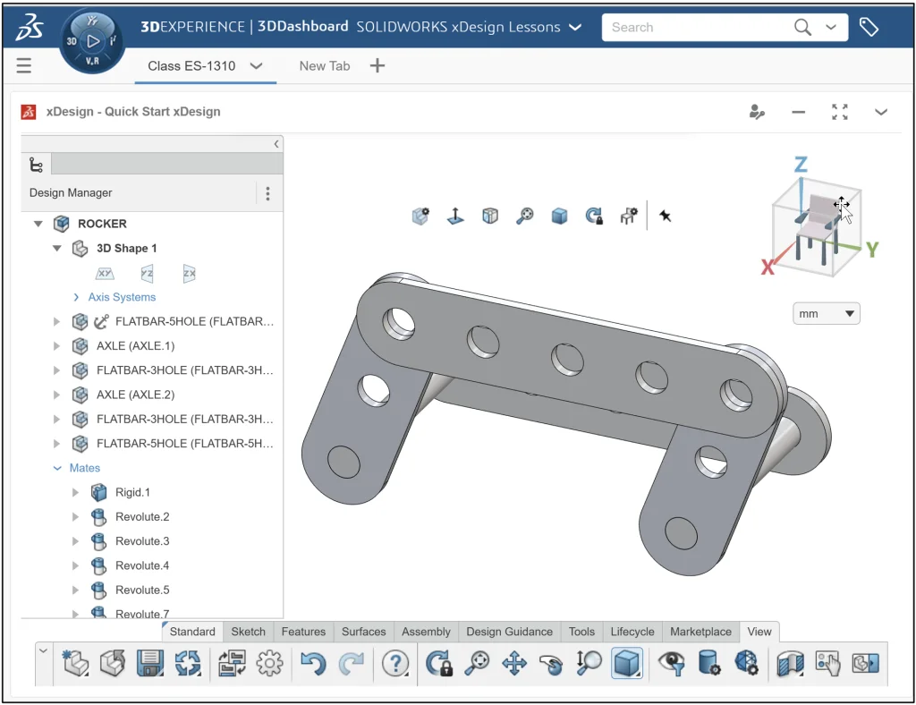
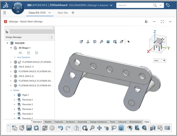
Rotate the ROCKER in a Trimetric View
Display a Trimetric view. View the model and the Design Manager.
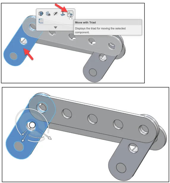
Rotate the Rocker.
Click the first FLATBAR-3HOLE component from the Design Manager.
Drag the large arc in the Triad. View the rotation of the ROCKER.
Click a position in the Work Area.
Return to the original position.
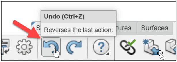
Click Undo for the Task bar.
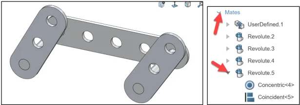
The Parallel Mate is not required. Delete the Parallel mate.
Right-click Parallel <1> from the Design Manager.
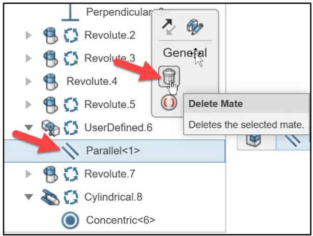
Click Delete Mate from the Content box.
View the updated Mate folder. The Mates, Rigid and Revolute correspond to the physical dynamics of a rigid body described by the laws of kinematics and by Newton’s Second Law or Lagrange mechanics (second derivative).
Note: Another way to view the component Triad is to click the component. Click Move with Triad. A Triad is displayed on the component.
Join a 3DEXPERIENCE Academic or Student Community
Academic Community: After you create a 3DEXPERIENCE ID, Educators, can get more information on xDesign and SOLIDWORKS. Request to join the 3DEXPERIENCE Academic Community for free at go.3ds.com/academiccommunity.
Student Community: Students, join the student community for free at go.3ds.com/studentcommunity. Check out great posts on Mechanism Mondays, Heritage Tuesdays, FEA Fridays, and Solid Saturdays (animations) and Formula SAE and Formula Student examples.
Next SOLIDWORKS xDesign Lesson
David’s next post is SOLIDWORKS xDesign Lesson #8: 4Bar Linkage and Kinematics
Previous Lessons
SOLIDWORKS xDesign Lesson #1: Getting Started
SOLIDWORKS xDesign Lesson #2: Mouse Control and Collaborative Space
SOLIDWORKS xDesign Lesson #3: Sketch Planes
SOLIDWORKS xDesign Lesson #4: Create A Dashboard
SOLIDWORKS xDesign Lesson #5: Views and Orientations
SOLIDWORKS xDesign Lesson #6: Importing Files and Using Bookmarks
Design well, Marie