

After teaching 1000’s of students and writing about SOLIDWORKS for over 25 years, David Planchard, emeritus WPI, is exploring xDesign. Through the SOLIDWORKS xDesign Lesson series, David helps educators understand the differences and similarities between xDesign and SOLIDWORKS through simple examples. He also introduces new apps in the engineering design process.
Create assemblies using the Bottom-up design approach, the Top-down design approach, or a combination of both methods. SOLIDWORKS uses both Bottom-up and Top-down design approaches. In the Top-down approach, when you create a part In-context, the part is virtual. The virtual part does not exist outside of the assembly.
xDesign is based on a systems engineering approach (single modeling environment) which is Top-down. The Physical Products (components) can be used between many apps on the 3DEXPERIENCE platform. In xDesign, the term component is used because both parts and assemblies are treated the same.
Create a Physical Product in xDesign. Insert components one at a time into the Physical Product. The first component is inserted to the Origin and is fixed. All other components are inserted to the Origin and are not fixed.
Click the Description link to download the needed components. Extract three SOLIDWORKS files. Import the three SOLIDWORKS files: (Part1, Part2, and Part4) into your xDesign Collaborative space. Apply the following mates: Concentric, Coincident, and Distance.
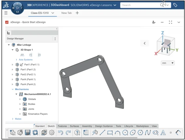
Create a 4Bar Linkage mechanism. A mechanism simulates the motion of different bodies through time. Create mechanisms under the Root Physical Product or under any Physical Product occurrence included in the model.
Apply the Kinematics player. Watch the movement of the 4Bar Linkage. The Kinematic player only works with joints, not mates.
The three default planes in xDesign are: xy (Top), yz (Front), and zx (Right). The three default planes in SOLIDWORKS are: Front, Top, and Right. This is a very important difference between SOLIDWORKS and xDesign when you insert a SOLIDWORKS part into xDesign. The orientation will be different.
Login to the 3DEXPERIENCE platform.
Start xDesign.
Click xDesign to launch the App or open an existing Dashboard with xDesign as a Widget. xDesign has a single modeling environment.
Create a New Component.
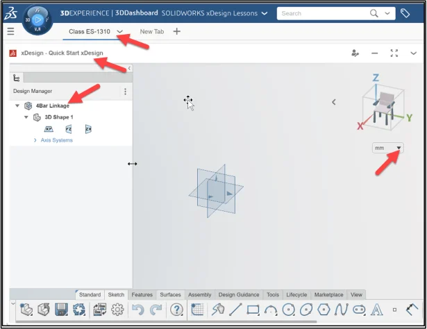
Name the New Root Component 4Bar Linkage.
Click 4BarParts to download the needed components.
Extract three SOLIDWORKS files. Import the three SOLIDWORKS files: (Part1, Part2, and Part4) into your xDesign Collaborative space. Note: AWindows model file cannot be directly opened in xDesign. The model file needs to be imported. You can only have one model open at a time.
In this lesson, my Collaborative space is Quick Start xDesign.
I created a Tab for an xDesign class, ES-1310.
The default units are in millimeters.
Insert the first component, Part1.
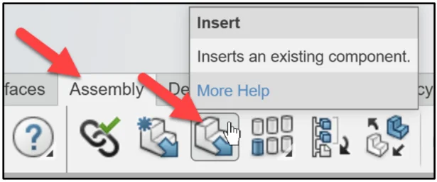
Click Insert from the Assembly tab in the Action bar.
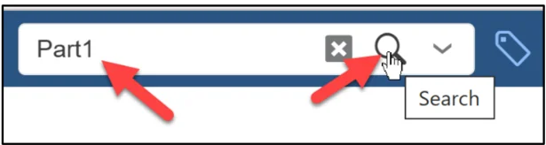
The Open box is displayed. Use Search and the 6W tags to find the imported SOLIDWORKS parts. Search for components as you would using Google. Search for Part1.
Enter Part1 in the Search box.
Click Search.
Click inside the Part1 box from the Results area.
Click OK.
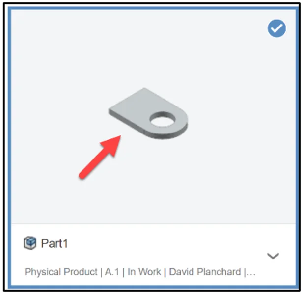
The Part1 component is inserted to the Origin. The first component is fixed aligned to the three default planes in xDesign.
Hide the default planes to improve clarity.
Click xy in the Design Manager.
Click Hide from the Content bar.
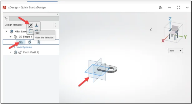
Repeat the hide process for the yz plane and zx plane.
Press the f key to fit the component to the Work Area.
The Part1 component is located at the Origin. It is not in the required orientation. Address the orientation using three mates.
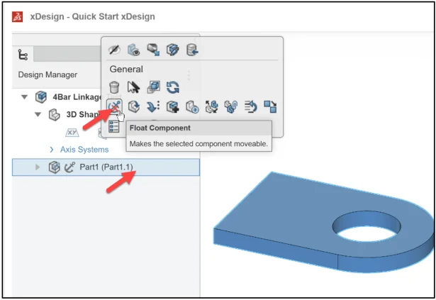
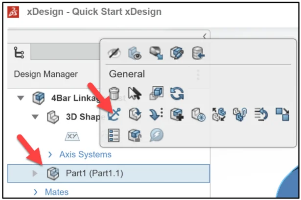
Right-click Part1 (Part1.1) in the Design Manager.
Click Float Component from the General Content box.
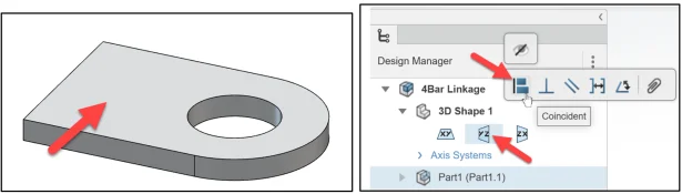
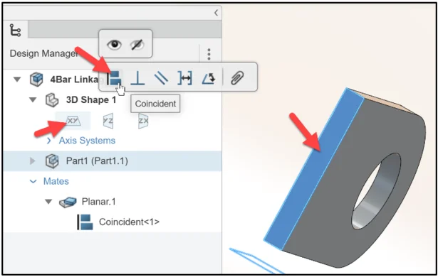
Insert the first mate. Insert a Coincident mate between the Top flat face of Part1 (Part1.1) and the yz plane of the 4Bar Linkage.
Click the Top flat face of Part1 (Part1.1). Hold the Ctrl key down. Click the yz plane of the 4Bar Linkage. Release the Ctrl key. The pop-up menu is displayed. Click Coincident. The Mate folder is added to the Design Manager. Coincident<1> is created.
Insert the second mate. Insert a Coincident mate between the Bottom flat face of Part1 (Part1.1) and the xy plane of the 4Bar Linkage.
Click the Bottom flat face of Part1 (Part1.1). Hold the Ctrl key down. Click the xy plane of the 4Bar Linkage. Release the Ctrl key. The pop-up menu is displayed. Click Coincident.
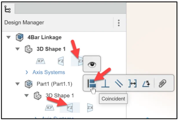
Insert the third mate to address the final orientation. Insert a Coincident mate between the yz plane of Part1 (Part 1.1) and the zx plane of the 4Bar Linkage.
Click the yz plane of Part1 (Part1.1). Hold the Ctrl key down. Click the zx plane of the 4Bar Linkage. Release the Ctrl key. The pop-up menu is displayed. Click Coincident.
Fix Part1 (Part1.1) to the Origin.
Right-click Part1 (Part1.1) from the Design Manager.
Click Fix Component from the Content box.
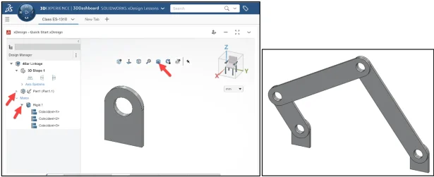
Display a Trimetric view. View the result. Remember the assembly you are creating and the location of the components.
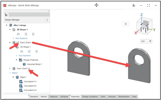
Insert the second component from the Design Manager.
Click Part1 (Part 1.1) from the Design Manager.
Hold the Ctrl key down.
Drag Part1 (Part 1.1) into the Work Area as illustrated.
Release the Ctrl key.
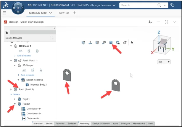
Release the mouse button. Part1 (Part1.2) is displayed in the Design Manager and in the Work Area.
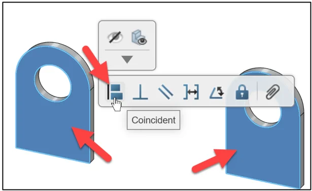
Insert a Coincident mate.
Click the Front flat face of Part1 (Part 1.2). Hold the Ctrl key down. Click the Front flat face of Part1 (Part 1.1). Release the Ctrl key. The pop-up menu is displayed. Click Coincident.
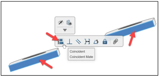
Insert a Coincident mate between the Bottom flat face of Part1 (Part 1.2) and the Bottom flat face of Part1 (Part 1.1). Note: It is a good practice to move and rotate components into their rough position first before adding mates.
Insert a Distance mate (220mm) between the Left flat face of Part1 (Part 1.2) and the Right flat face of Part1 (Part 1.1).
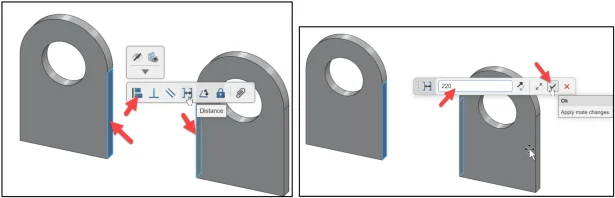
Press the f key to fit the model to the Work Area. Display a Trimetric view.
Insert the third component, Part2.
Click Insert from the Assembly tab in the Action bar.

The Open box is displayed.
Enter Part2 in the Search box. Click Search.
Click inside the Part2 box from the Results area.
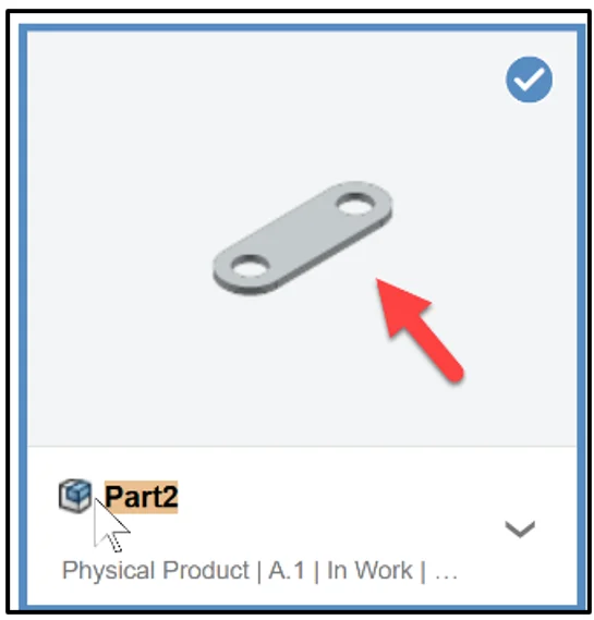
Click OK.
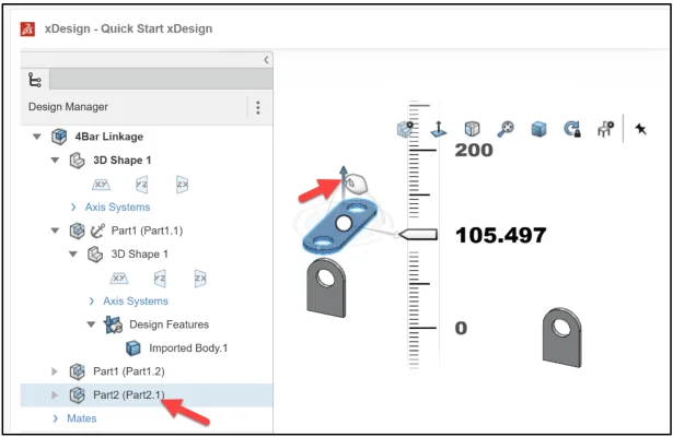
Part2 is inserted to the Origin. Look at the Origin first to locate components when creating mates. Part2 (2.1) is not fixed.
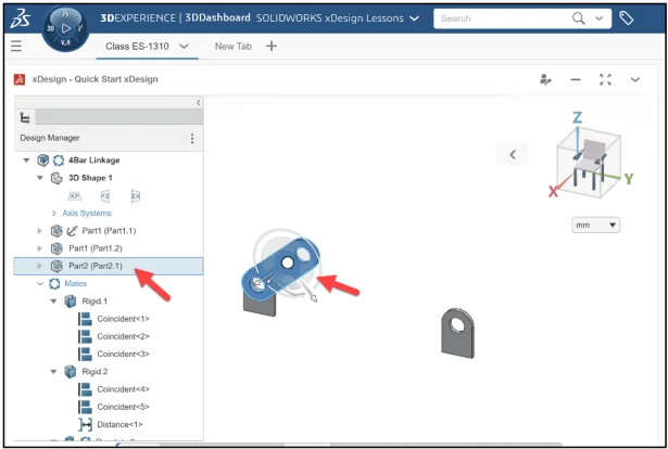
Display the Triad of Part2.
Click Part2 (2.1) from the Design Manager. A Triad is displayed on Part2 (2.1) in the Work Area.
Use the Triad’s direction arrows to move the component linearly and the small and large arcs to rotate the component.
Take your time to zoom in/out and fit the components to the Work Area. This will help to select the correct faces and edges for the mating process.
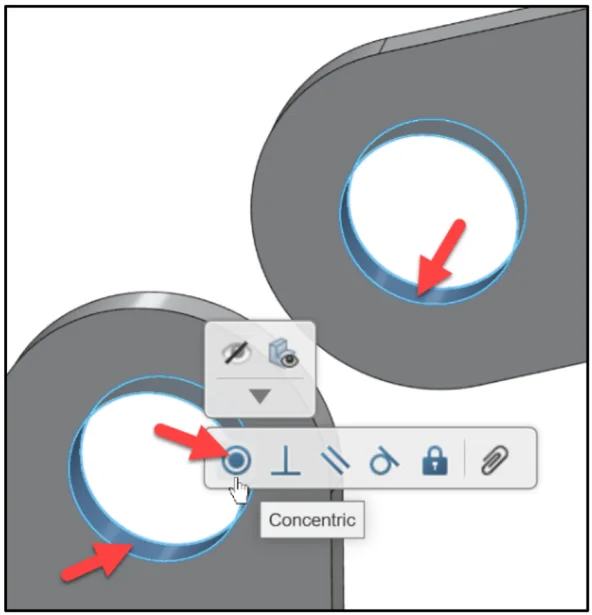
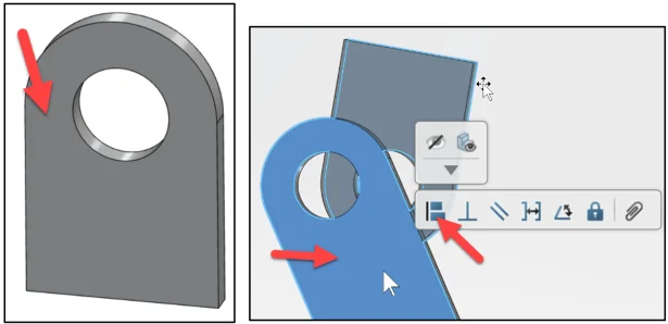
Insert a Concentric mate between the inside cylindrical face of Part1 (Part1.1) and the first cylindrical face of Part2 (Part2.1).
Insert a Coincident mate between the Front flat face of Part1 (Part1.1) and the Back flat face of Part2 (Part2.1).
Display a Trimetric view. Rotate Part2 (Part2.1) upward as illustrated.
Save the 4Bar Linkage.
Insert the fourth component, Part4.
Click Insert from the Assembly tab in the Action bar.
The Open box is displayed.
Enter Part4 in the Search box. Click Search.
Click inside the Part4 box from the Results area. Click OK.
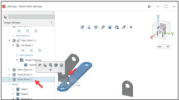
The Part4 is inserted to the Origin. Display the Triad of Part4 (Part4.1).
Click Part4 (Part4.1) from the Design Manager. A Triad is displayed on Part4 (Part4.1) in the Work Area.
Use the Triad’s direction arrows to move the component linearly and the small and large arcs to rotate the component.
Insert a Concentric mate between the first cylindrical face of Part4 (Part4.1) and the last cylindrical face of Part 2 (Part2.1).
Insert a Coincident mate between the Back flat face of Part4 (Part4.1) and the Front flat face of Part2 (Part2.1).
Press the f key to fit to the Work Area.
Display in a Trimetric view.
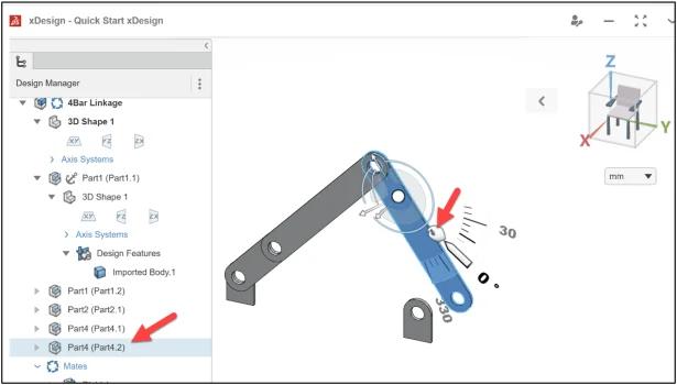
Click Part4 (Part4.1) in the Design Manager.
Move Part4 (Part4.1) using the Triad as illustrated.

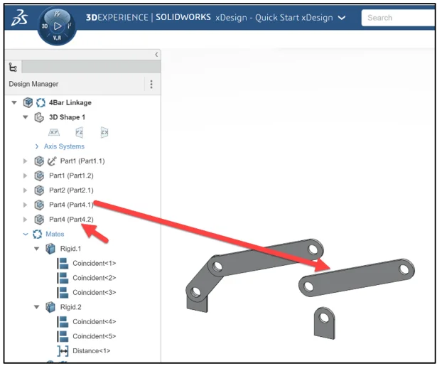
Insert a component from the Design Manager.
Click Part4 (Part4.1) from the Design Manager. Hold the Ctrl key down. Drag Part4 (Part4.1) into the Work Area as illustrated. Release the Ctrl key. Release the mouse button. Part4 (Part4.2) is displayed in the Design Manager and in the Work Area.
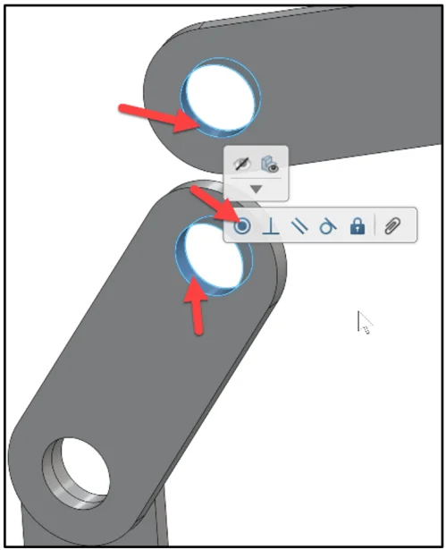
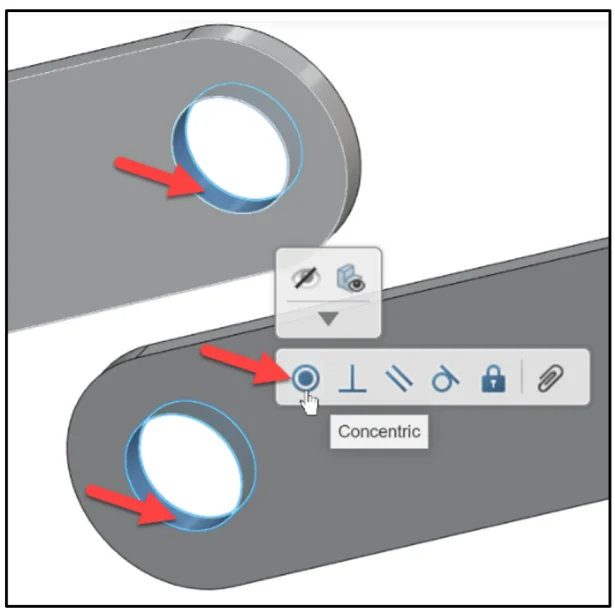
Insert a Concentric mate between the first cylindrical face of Part4 (Part4.2) and the last cylindrical face of Part4 (Part4.1).
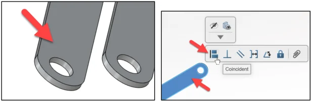
Insert a Coincident mate between the Back flat face of Part 4 (Part4.1) and the Front flat face of Part4 (Part4.2).
Press the f key to fit to the Work Area.
Display a Trimetric view.
Click Part4 (Part4.2) in the Design Manager. A Triad is displayed on Part4 (Part4.2).
Move Part4 (Part4.2) using the Triad. It is a good practice to move and rotate components into their rough position first before adding mates.
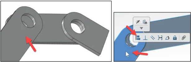
Insert a Concentric mate between the cylindrical face of Part4 (Part4.2) and the cylindrical face of Part1 (Part1.2).
Insert a Coincident mate between the Back flat face of Part4 (Part4.2) and the Front flat face of Part1 (Part1.2).
Press the f key to fit to the Work Area.
Display in a Trimetric view.
Click Part2 (Part2.1) in the Design Manager. A Triad is displayed on Part2 (Part2.1).
Move Part2 (Part2.1) using the Triad. View the result.
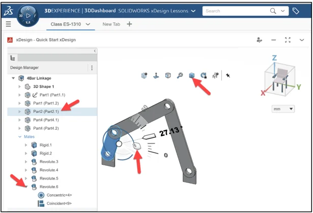
Click in the Work Area.
In the next section create a mechanism to simulate the motion of the 4Bar Linkage over time. Create mechanisms under the root product or under any product occurrence included in the model.
Your physical product or component assembly must include angle or distance mates to simulate movement.
Define mechanisms using products and mates.
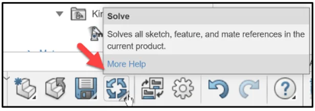
Click Mechanism from the Tools tab in the Action bar. Note: Click More Help for additional information and engineering mechanics definitions.
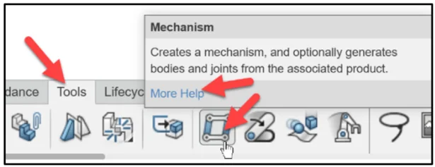
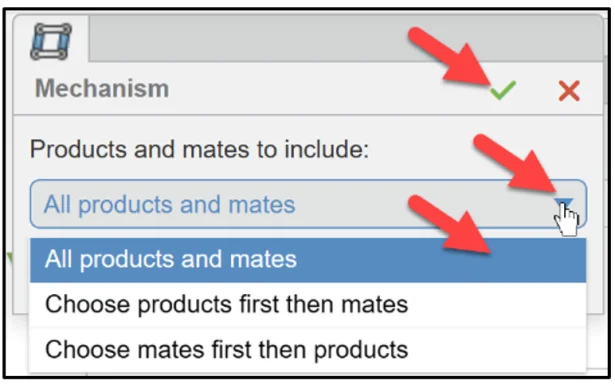
The Mechanism dialog box is displayed.
Select All products and mates.
Click OK.
Save the 4Bar Linkage.
The Mechanism folder is created.
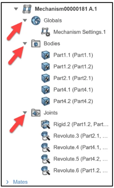
Expand the Mechanism folder.
Three elements are created: Globals, Bodies, and Joints.
The Globals node includes the Mechanism setting. To edit the Mechanism setting, open the model in one of the Motion Apps.
The Bodies node includes all of the bodies created in the Mechanism.
The Joints node includes all of the Joints created in the Mechanism.
In the next section, create a Kinematic Player. The Kinematic Player provides the ability to animate bodies and component assemblies by controlling the degrees of freedom (DOF) of the joints enforced in the mechanism. An assembly has 6 degrees of freedom, 3 translational and 3 rotational.
Click SOLVE from the Standard tab in the Action bar.
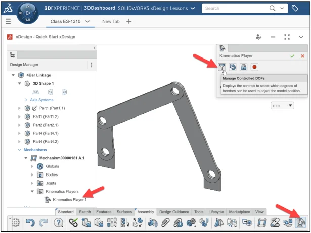
Click Kinematic Player from the Tools tab in the Action bar.
The Kinematic Player dialog box is displayed.
Display a list of degrees of freedom (DOF) that you can control.
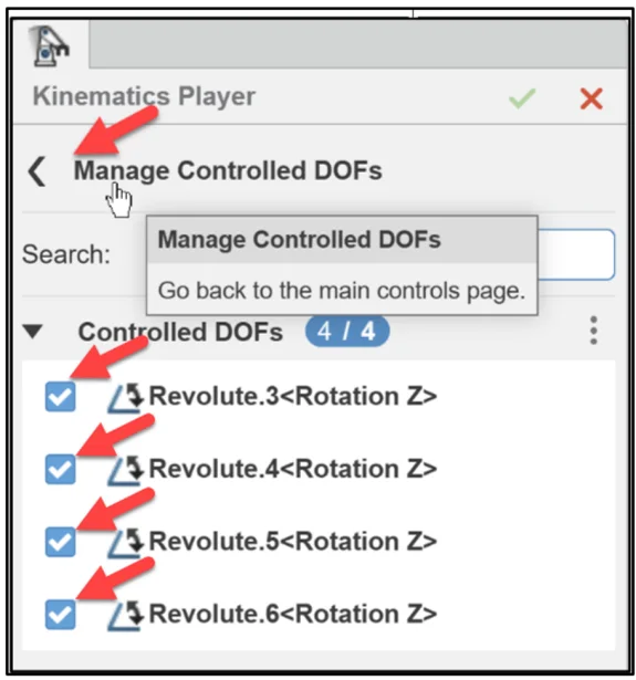
Click Manage Controlled DOFs.
Select the 4 degrees of freedom as illustrated.
Click Manage Controlled DOFs.
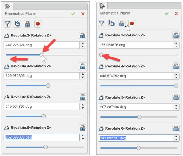
Move the Revolute.3
Create the animation and record.
Click Record Animation.
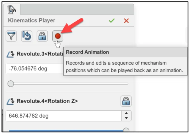
The Animation player is displayed.
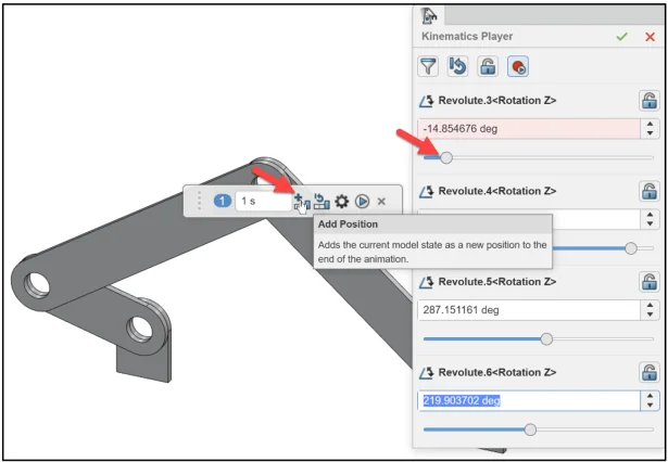
Move the Revolute.3
Click the Add Position icon. A position of the animation is created.
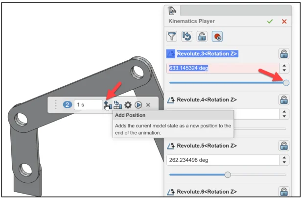
Move the Revolute.3
Click the Add Position icon. A position of the animation is created.
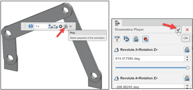
Click the Play icon. View the animation in the Work Area.
Save the animation. Close the Animation player. Close the Kinematics Player.
Click OK from the Kinematics Player.
We are finished with the lesson.
In the next Assembly lesson, External References and Copy with Mates are addressed.
Academic Community: After you create a 3DEXPERIENCE ID, Educators, can get more information on xDesign and SOLIDWORKS. Request to join the 3DEXPERIENCE Academic Community for free at go.3ds.com/academiccommunity.
Student Community: Students, join the student community for free at go.3ds.com/studentcommunity. Check out great posts on Mechanism Mondays, FEA Fridays, Solid Saturdays (animations), Formula Student and Formula SAE exercises.
Stay tuned for David’s next SOLIDWORKS xDesign Lesson #9: 4Bar External References
To review the previous lessons, go to:
SOLIDWORKS xDesign Lesson #1: Getting Started
SOLIDWORKS xDesign Lesson #2: Mouse Control and Collaborative Space
SOLIDWORKS xDesign Lesson #3: Sketch Planes
SOLIDWORKS xDesign Lesson #4: Create A Dashboard
SOLIDWORKS xDesign Lesson #5: Views and Orientations
SOLIDWORKS xDesign Lesson #6: Importing Files and Using Bookmarks