
After teaching 1000’s of students and writing about SOLIDWORKS for over 25 years, David Planchard, emeritus WPI, is exploring xDesign. Through the SOLIDWORKS xDesign Lesson series, David helps educators understand the differences and similarities between xDesign and SOLIDWORKS through simple examples. He also introduces new apps in the engineering design process.
One of the most important concepts in CAD modeling is building in the correct design intent.
Design Intent
All designs are created for a purpose. Design intent is the intellectual arrangement of sketches, constraints, dimensions, and features of a design. Design intent manages the relationship between sketches in a feature, features in a part, and parts in an assembly.
A definition of design intent is the process in which the model is developed to accept future modifications. Models behave differently when design changes occur.
Build design intent in a sketch as the profile is created. A profile is determined from Sketch entities. Example: Rectangle, Circle, Arc, Point, Slot, etc. Note: xDesign uses the name Sketch entities. SOLIDWORKS uses the name Sketch tools.
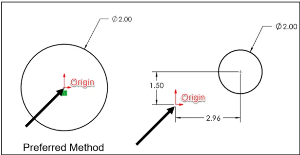
Apply symmetry into a profile through a sketch centerline, mirror entity and position about the reference planes and Origin. Always know the location of the Origin in the sketch.
You should have a design strategy with your sketch profiles as you create the 3D features for the component.
Login to the 3DEXPERIENCE platform.
Start xDesign.
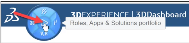
Click the center of the Compass as illustrated for Roles, Apps & Solutions portfolio.
Click 3D Designer (3D Creator) under the My Roles (xDesign).
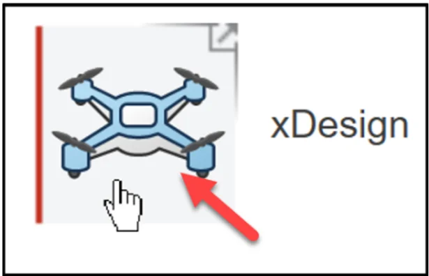
Click xDesign to launch the App. The xDesign App creates components in a single modeling environment. The term component is used because both parts and assemblies are treated the same. This is not true in SOLIDWORKS.
The default Name* of the component is Physical Product 1.
The default Location defines the Collaborative space (cloud storage) where your components are saved. This makes it easy to communicate and share designs with your students and team members, regardless of physical location.
The default Location maybe named: Common Space. Collaborative space location will differ depending on setup.
The 3DSpace App is used to create Collaborative space locations. The Quick Start xDesign Collaborative space and the 3DEXPERIENCE mouse control is used in the lesson.
Create a new component
Click New Component.
Rename component to Revolved Pin.
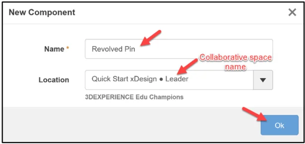
Click OK.
The xDesign App is displayed.
Trimetric Planes xy, yz, zx are located at the center of the Work Area.
The default axes are: +x, +y, +z
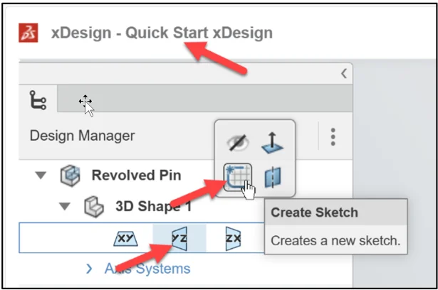
Create Sketch.1. Sketch.1 is normal to the yz plane (Front). Quick Start xDesign is the Collaborative space. When you create a new component, the three default planes (xy), (yz), (zy) are aligned with specific views. The plane you select for your first sketch determines the orientation of the part. Selecting the correct plane to start your model is very important.
Click the yz plane in the Design Manager.
Click Create Sketch from the Context toolbar.
Create a horizontal line through the Origin along the y axis.
Click Line from the Sketch tab in the Action bar.
Click a horizontal position to the left of the Origin as illustrated.
Click a horizontal position to the right through the Origin as illustrated.
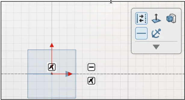
Deactivate the Line entity.
Press the Esc key. Note: Can can also double-click to deactivate the Line. The sketching process is straight forward as it is in SOLIDWORKS.
Click the horizontal line as illustrated. The Coincident and Horizontal callout icons are displayed. This is similar in SOLIDWORKS.
Change the horizontal line to an Infinite line. Use the Infinite line as the axis of revolution for the Revolve Feature. Note: You can also use a Construction line as an axis of revolution. The Construction line must be dimensioned relative to other geometry to be fully defined. This is not the case in SOLIDWORKS.
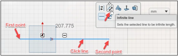
Click Infinite line in the Context toolbar.
Create the Sketch profile
Click Line from the Action bar.
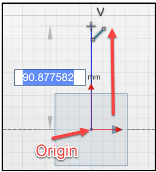
Click the Origin. Sketch the first vertical line above the Origin as illustrated.
Click a point approximately 90mm. A V (Vertical constraint) is displayed during the sketch process.
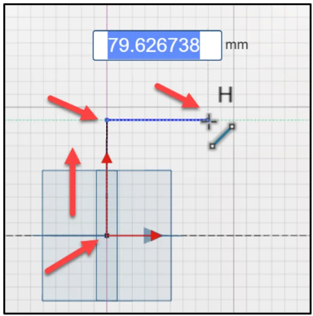
Sketch a horizontal line from the endpoint of the first vertical line.
Click a point approximately 80mm. A H (Horizontal constraint) is displayed during the sketch process.
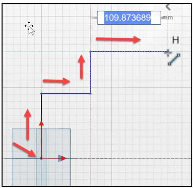
Sketch the second vertical line.
Click a point approximately 60mm.
Sketch the second horizontal line.
Click a point approximately 110mm.
Complete the sketch profile as illustrated. Note: Create a closed sketch. The end point is the Origin. At this time, do not worry about dimensions for the other lines.
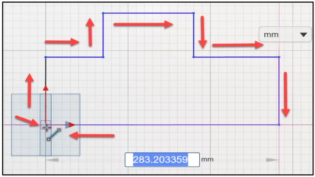
Deactivate Line.
Press the Esc key.
A good practice is to first add sketch constraints and then dimensions to a sketch.
Add Constraints
Add the first Equal constraint to the left and right vertical lines.
Click the left vertical line. Do not click the midpoint.
Hold the Ctrl key down.
Click the right vertical line. Do not click the midpoint.
Release the Ctrl key.
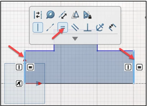
Click Equal from the Constraints toolbar.
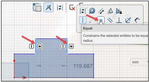
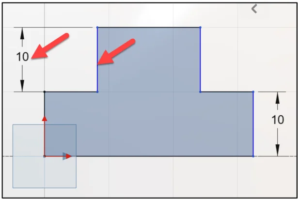
Add the second Equal constraint to the top left vertical line and the top right vertical line.
Click the top left vertical line. Do not click the midpoint.
Hold the Ctrl key down.
Click the top right vertical line. Do not click the midpoint.
Release the Ctrl key.
Click Equal from the Constraints toolbar.
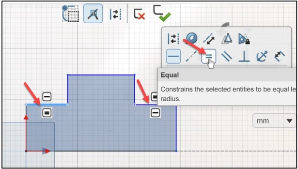
Add the third Equal constraint to the left and right horizontal lines.
Click the left horizontal line. Do not click the midpoint.
Hold the Ctrl key down.
Click the right horizontal line. Do not click the midpoint.
Release the Ctrl key.
Click Equal from the Constraints toolbar.
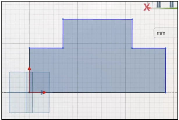
Deselect the constraints.
Press the Esc key.
Note: To delete an existing constraint, click on the entity. Click the contraint. Click Delete.
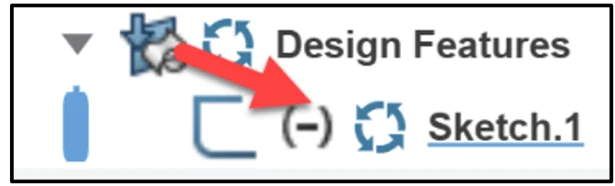
At this time, Sketch.1 is underdefined. The under define sketch symbol (-) is the same as SOLIDWORKS.
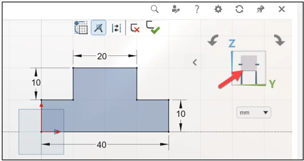
Dimension the sketch
There are many different ways to insert dimensions.
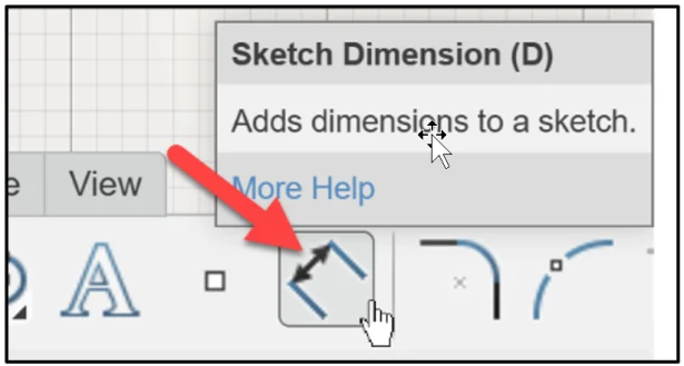
Click Sketch Dimension from the Action bar.
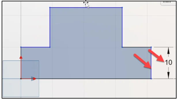
Click the right vertical line (not the midpoint).
Click a position to the right.
Enter 10.
Click the second vertical line (not the midpoint).
Click a position to the left.
Enter 10.
Click the top horizontal line (not the midpoint).
Click a position above the line.
Enter 20.
Click the bottom horizontal line (not the midpoint).
Click a position below the line.
Enter 40.
Deactivate Sketch Dimension.
Press the Esc key.
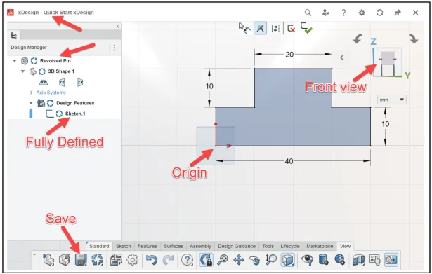
Sketch.1 is displayed in black and is fully defined.
Press the f key to fit the sketch to the Work Area.
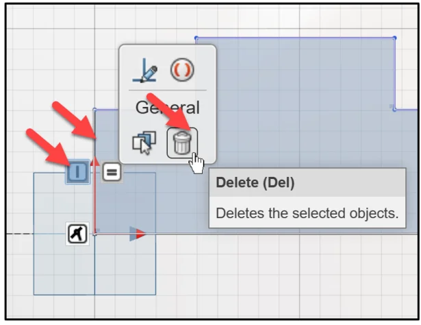
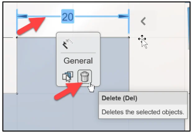
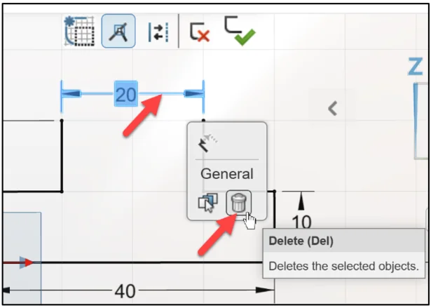
Note: To delete a dimension, click the leader line of the dimension. Click Delete from the General Context toolbar.
Save the component.
Click Save from the Action bar.
Create a Revolve feature
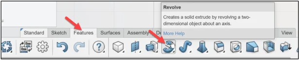
A Revolve is a sketch base feature. A Revolve feature adds material. The Revolve feature requires an infinite line or centerline and a sketch profile on a Sketch plane. A Revolve feature requires an angle of revolution. The sketch is revolved around the infinite line or centerline.
Click Revolve from the Action bar.
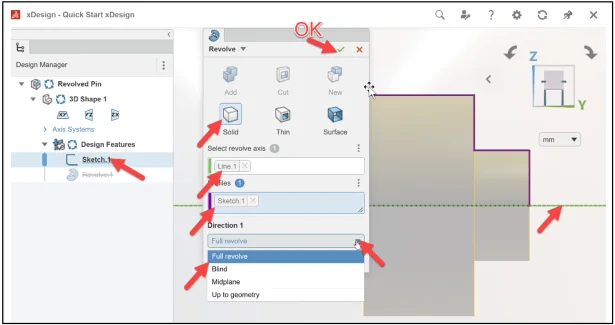
The Revolve dialog box is displayed.
Solid is selected by default.
Click the Infinite line in the Work Area. Line.1 is displayed in the Select revolve axis box.
Click Sketch.1 from the Design Manager. Sketch.1 is displayed in the Profiles box.
Select Full revolve for Direction 1.
Click OK (green checkmark) to complete the task.
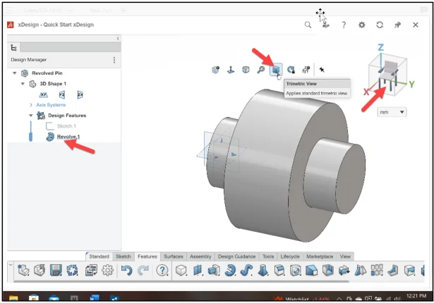
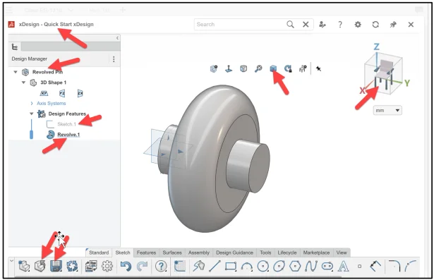
Display a Trimetric View.
Click Trimetric View from the expansion arrow in the Work Area. Revolve.1 is created. Sketch.1 is fully defined.
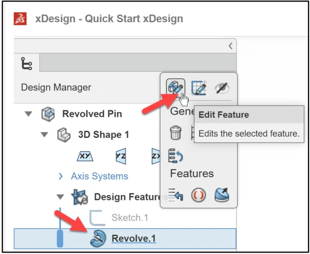
Note: To edit an existing feature, click the feature in the Design Manager, select Edit Feature in the Context toolbar.
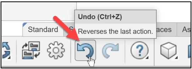
Note: Click Undo or Redo in the Action bar to reverse or recover the last action.
Modify Sketch.1. Delete the top vertical line. Insert a 3 Point Arc.
Insert a Tangent constraint.
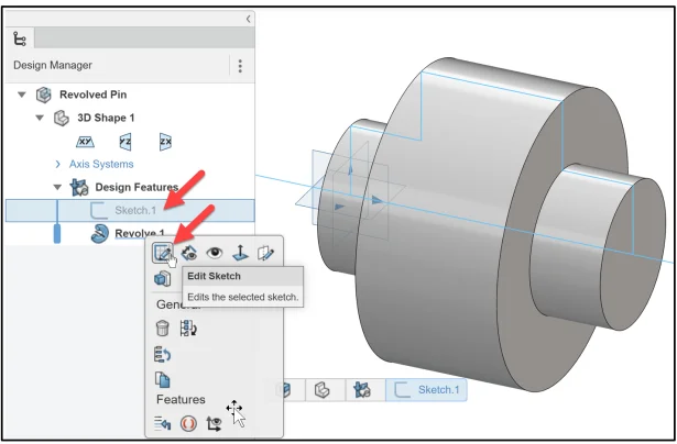
Right-Click Sketch.1 in the Design Manager. The General tools are displayed.
Click Edit Sketch in the Content toolbar.
Display a Front view using the Triad.
Click the yz face in the Triad as illustrated.
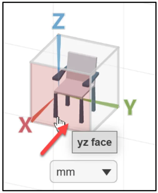
Front view is displayed.
Edit a Sketch
Delete the top vertical line.
Click the top vertical line.
Click Delete from the General drop-down Context box. Note: You can also press the Delete button.
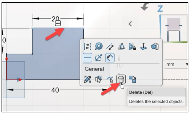
The Equal constraint remains on the two vertical lines maintaining design intent of the sketch.
Delete the 20mm dimension.
Click the 20 leader line.
Click Delete from the General drop-down Context box.
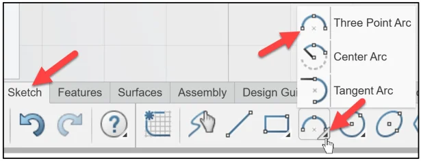
Apply the Three Point Arc Sketch entity.
Click Three Point Arc from the Action bar.
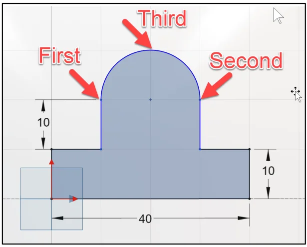
Click the first point as illustrated.
Click the second point as illustrated.
Click the third point as illustrated.
Deactivate the Three Point Arc sketch entity.
Press the Esc key.
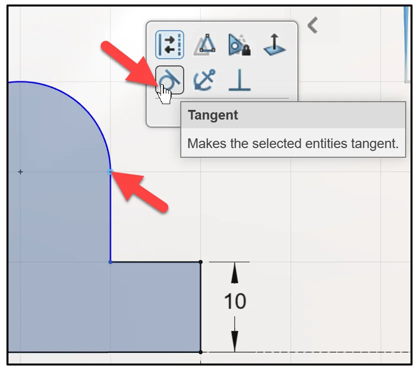
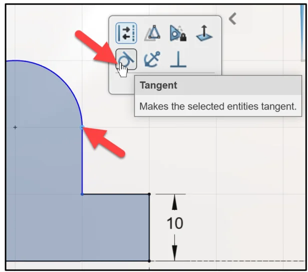
Insert two Tangent constraints between the vertical lines and the arc.
Click the first point.
Click Tangent from the Context box.
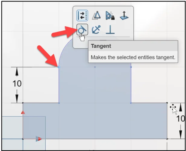
Click the second point.
Click Tangent from the Context box.
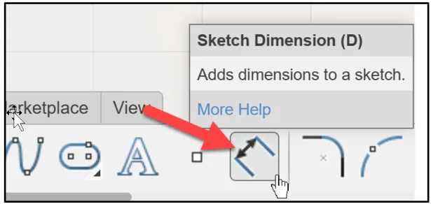
Dimension the Arc.
Click Sketch Dimension from the Action bar. View the Sketch Dimension icon.
Click the Arc.
Click a position above the Arc.
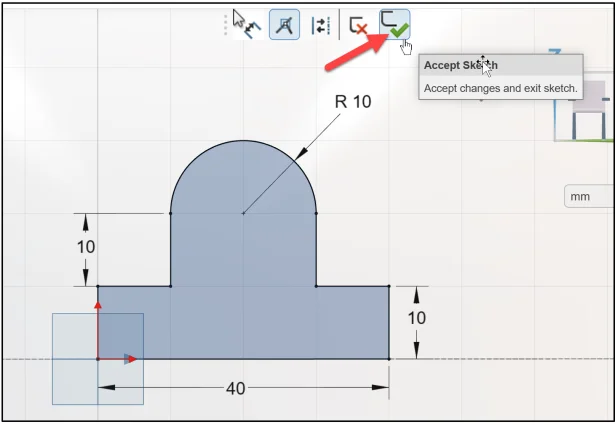
Enter 10. The dimension displays R to indicate radius.
Deactivate the Sketch Dimension.
Press the Esc key.
Accept the Sketch and exit.
Click Accept Sketch.
Display a Trimetric View.
Click Trimetric View from the expanded arrow in the Work Area.
Sketch.1 is fully defined. The Revolved Pin component is finished.
Save and Close the model.
There are different techniques in xDesign to dimension a sketch.
Option 1: As you sketch, the Dimension Edit Box is displayed. Click the sketch entity. Enter the dimension in the Dimension Edit Box.
Option 2: Click the sketch entity. Click Distance from the Context toolbar. Enter the distance. This constrains the distance between the selected entities.
Option 3: Click Sketch Dimension in the Action bar. Click the sketch entity. Click a position to enter the dimension. Enter the dimension. This option provides the ability to place and move the dimension.
Academic Community: After you create a 3DEXPERIENCE ID, Educators, can get more information on xDesign and SOLIDWORKS. Request to join the 3DEXPERIENCE Academic Community for free at go.3ds.com/academiccommunity.
Student Community: Students, join the student community for free at go.3ds.com/studentcommunity. Check out great posts on Mechanism Mondays, FEA Fridays, Solid Saturdays (animations), Formula Student and Formula SAE exercises.
Stay tuned for David’s next SOLIDWORKS xDesign Lesson #11: Features
To review the previous lessons, go to:
SOLIDWORKS xDesign Lesson #1: Getting Started
SOLIDWORKS xDesign Lesson #2: Mouse Control and Collaborative Space
SOLIDWORKS xDesign Lesson #3: Sketch Planes
SOLIDWORKS xDesign Lesson #4: Create A Dashboard
SOLIDWORKS xDesign Lesson #5: Views and Orientations
SOLIDWORKS xDesign Lesson #6: Importing Files and Using Bookmarks
SOLIDWORKS xDesign Lesson #7: Assemblies
SOLIDWORKS xDesign Lesson #8: 4Bar Linkage and Kinematics
SOLIDWORKS xDesign Lesson #9: External References and Copy with Mates