
After teaching 1000’s of students and writing about SOLIDWORKS and SOLIDWORKS Simulation for over 25 years, David Planchard, emeritus WPI, is exploring 3DEXPERIENCE Simulation and the Abaqus solver. Through the SOLIDWORKS and 3DEXPERIENCE Simulation Lesson series, David helps educators understand 3DEXPERIENCE Simulation fundamentals through simple examples and industry practices.
Dassault Systèmes owns SOLIDWORKS and various simulation software packages. Simulation packages range from SOLIDWORKS Simulation, CATIA Analysis, Abaqus and many others. All of them are under the SIMULIA family.
Why do I teach my first year engineering students about simple stress analysis using 3DEXPERIENCE Simulation? I want them to get excited about their more advanced classes over the next 4 years.
Learning the theory to derive complex formulas to understand the variables is essential, but getting early exposure to simulation software, brings theory to reality with instant visualizations and what-ifs. This shows the students the potential of using simulation in the real world.
In this lesson, learn the proper workflow to upload a SOLIDWORKS part to the 3DEXPERIENCE platform and perform a Static Linear Simulation study using the Abaqus solver.
Open a SOLIDWORKS part that has not been saved to the 3DEXPERIENCE platform. Upload the part to the 3DEXPERIENCE platform. Save the part in your Collaborative space. Use an existing Bookmark. Return to your SOLIDWORKS desktop. Lock the part.
Launch the Linear Structural Validation App from the SOLIDWORKS Task Pane. Set Simulation Study preferences. Understand how to modify the default solver units. Run a Structural analysis. Set Study conditions: Mesh type (Tetrahedron second-order elements), Material (Alloy Steel), Fixed Displacement Restraint (three holes) and Load (13300N Force).
Create three plots: Von Mises Stress, Displacement, and Factor of Safety. Review the plots to interpret the results. Save the simulation in your Collaborative space.
3DEXPERIENCE Engineer in Education contains the entire 3DEXPERIENCE Works Structural Simulation portfolio.
Launch the 3DEXPERIENCE Platform and start SOLIDWORKS
Before we start, there are a few items that you need to know.
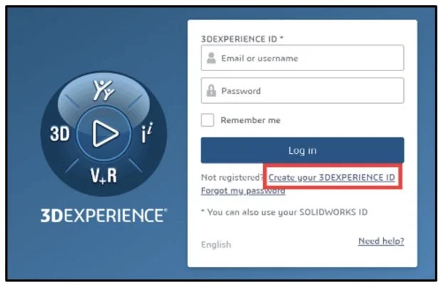
In this lesson, use your default Collaborative space. An internet connection is required. A 3DEXPERIENCE ID is required.
The Simulation lesson provides a foundation to users who are new to using simulation to solve real-word engineering and design problems. A Solid body is used. You should have a basic understanding of Stress and Finite Element Method (FEM).
3DEXPERIENCE Launcher needs to be installed. 3DEXPERIENCE Works Lesson 1: Getting Started with SOLIDWORKS.
The 3DEXPERIENCE platform is browser driven. Your existing cookies and cache determine what you will see on your computer desktop or during a SOLIDWORKS login. A full installation of SOLIDWORKS 2019 SP0 or later is required.
Start a SOLIDWORKS session from your desktop.
Double-click the SOLIDWORKS icon.
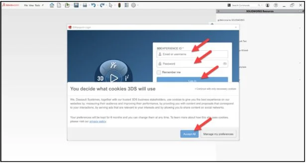
View the illustration below. Depending on your system setup, cookies, and cache, it will be different. Read the provided information.
Input the requested data.
Click Accept All.
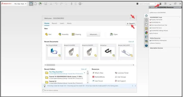
The Welcome – SOLIDWORKS dialog box is displayed.
You are logged into the 3DEXPERIENCE platform.
Close the Welcome dialog box.
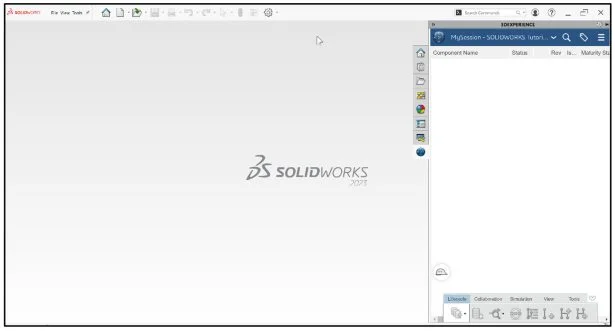
Click the 3DEXPERIENCE icon in the Task Pane. The MySession panel is displayed. This displays the two-way communication between SOLIDWORKS running on your desktop and the 3DEXPERIENCE platform running in the cloud.
In this lesson, I’m using a Collaborative space named Quick Start xDesign.
Note: If you do not see the 3DEXPERIENCE icon, click the Options drop-down arrow, click Add-Ins, check the 3DEXPERIENCE box, click OK, from the SOLIDWORKS Main menu.
Click Accept All.
Download Model 8-6
Download the SOLIDWORKS part, Model 8-6 to follow along with this lesson.
Open Model 8-6 that has not been previously uploaded or saved to the 3DEXPERIENCE platform.
Expand the Task Pane bar. The MySession panel displays a tree view of the active file and a list of commands that can be accessed through the Action bar and context menu.
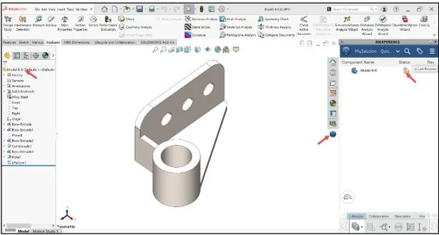
The orange save Status icon for Model 8-6 informs you that the local file on your computer has not been saved to the platform. Save the part to the 3DEXPERIENCE platform.
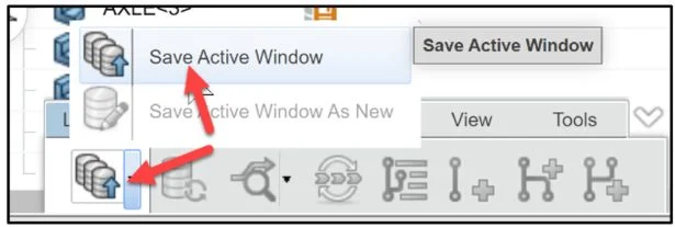
Click Save Active Window from the Lifecycle tab in the Action bar.
The file is temporarily being saved to a local cache area. The platform is checking for out of date components, modified components from the last save to the platform, different revisions, missing components, etc.
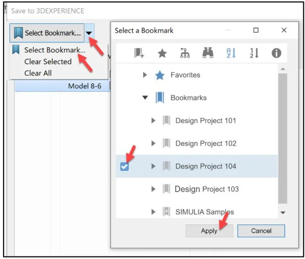
Select Bookmark
The Save to 3DEXPERIENCE dialog box and PLM attributes are displayed.
Save the model. Use your existing Collaborative space. Use an existing Bookmark. Note: If needed view 3DEXPERIENCE Works Lesson 3: SOLIDWORKS and Bookmarks, Share and Delete.
Click the Select Bookmark down arrow.
Click Select Bookmark. The Select a Bookmark dialog box is displayed.
In the below example, I selected Design Project 104 as my bookmark.
Click Apply from the Select a Bookmark dialog box.
Click Save from the Save to 3DEXPERIENCE dialog box.
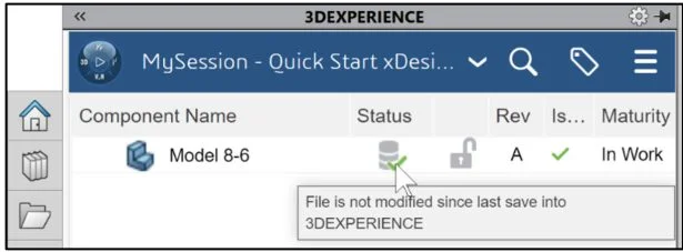
The model is directly loaded into your Collaborative space and Bookmarked on the 3DEXPERIENCE platform. You return back into your SOLIDWORKS desktop session.
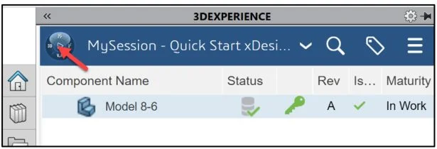
View the Status column in the updated MySession panel. The Status icon displays a green check mark. This means that the current file on your SOLIDWORKS desktop is updated and saved to the platform. The default Revision is A. The Maturity State is “In Work”. This is the default Lifecycle state after you saved the model to the 3DEXPERIENCE platform.
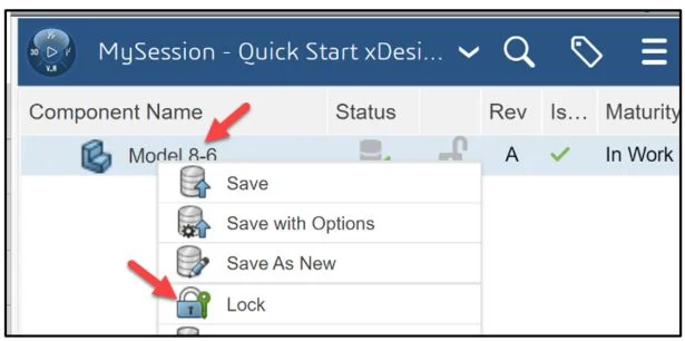
Lock the part. This prevents anyone else in making a change to it.
Right-click Model 8-6 in the MySessionPanel.
Click Lock. The lock icon is displayed. Model 8-6 is selected.
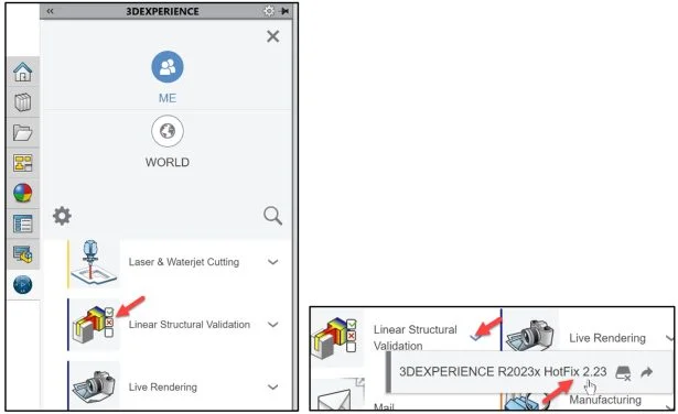
Linear Structural Validation App
Click the center of the Compass. Use the Linear Structural Validation App. Think of this App as the SOLIDWORKS Simulation Add-in inside of SOLIDWORKS. Most of the 3DEXPERIENCE Apps run in your web browser. 3DEXPERIENCE Simulation Apps perform a small installation on your windows machine. Both types of Apps are linked to your PLM data on the platform. The Linear Structural Validation App provides the ability to run Linear Structural, Buckling, Frequency, and Thermal Simulation studies.
Drag the slider downward to view the Linear Structural Validation App.
Launch the Linear Structural Validation App. Note: If this is your first time using a 3DEXPERIENCE Simulation App, download the needed App information on your computer.
This can take 10 – 15 seconds.
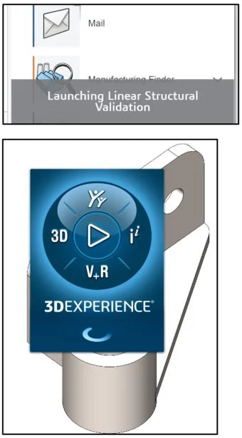
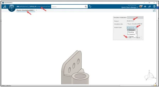
The 3DEXPERIENCE | SIMULIA Linear Structural Validation App is displayed.
Except the default Simulation title.
Select Structural from the Analysis type drop-down menu.
Click OK from the Simulation initialization dialog box. In a Linear analysis, there is a linear relationship between the applied loads and the induced response of the component. In a Nonlinear analysis the response of the component is not a linear function of the magnitude of the applied loads.
The Action bar is displayed.
Use a View tool to move the model in the center of the window.
View the Orientation of the Triad.
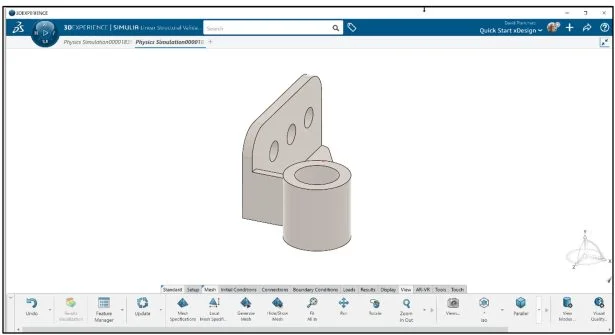
Rename the default Simulation title. The default title is Physics Simulation 00001853.
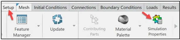
Setup Simulation Properties
Click the Setup tab in the Action bar.
Click Simulation Properties.
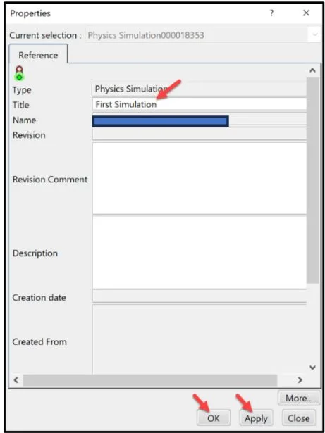
The Properties dialog is displayed. View your options for input.
Enter a new Title. In this example, I entered First Simulation.
Click Apply. Click OK from the Properties dialog box.
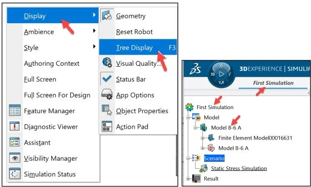
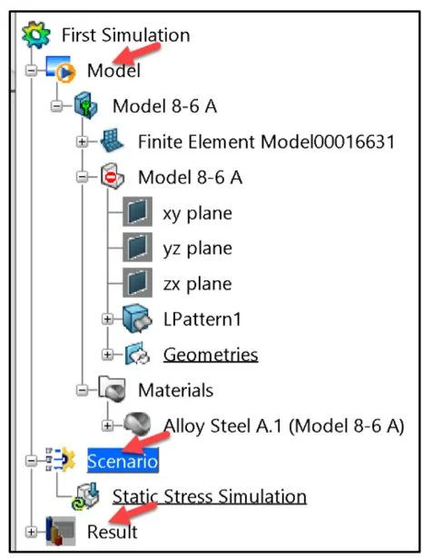
Display the First Simulation Study tree.
Right-click in the Graphics area.
Click Display. Click Tree Display.
The Simulation Study tree displays the Structural Simulation Process. Model (Geometry, Meshing (Element Family), and Property Definition). Scenario (Simulation Type, Solution Method, Element Type, Boundary Conditions, Loads, and Solver). Result (Types of plots, Animations and Tools).
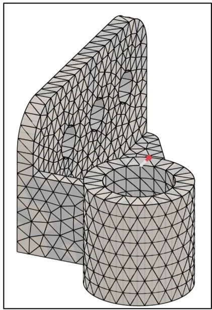
Apply Mesh
Apply a Global mesh. Use the default element type (Tetrahedron second-order elements). Mesh refinement is very important in regions of high stress concentrations such as regions of contact or sharp corners. Typically a smaller element size yields more accurate results, but increases the run time.
Click the Mesh tab in the Action bar.
Click Generate Mesh. Meshing splits continuous geometric models into finite elements. The types of elements created by this process depend on the type of geometry meshed. In this example a solid element (Continuum) – solid geometry is used.
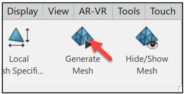
The mesh is displayed on the model.
Units and Preferences
View the default solver units and preferences.
Click your profile picture (Avatar).
Click Preferences from the drop-down menu.
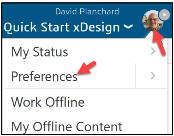
The Preference dialog box is displayed. View your options.
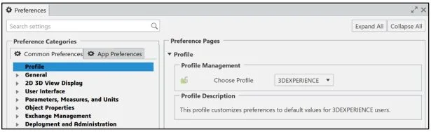
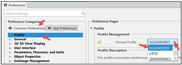
Modify the mouse profile from the default (3DEXPERIENCE) to SOLIDWORKS.
Click the Common Preferences tab.
Click Profile.
Select SOLIDWORKS from the drop-down menu under Profile Management.
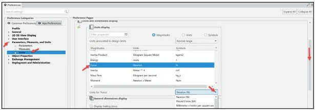
View the default Parameters, Measures, and Units in the Abaqus solver. The unit Force in the study is Newton.
Expand the Parameters, Measures, and Units column.
Click Units.
Click Force. The default Force unit is Newton.
Note: To modify a default unit, drag the slider downward to locate the magnitude, select the magnitude, select the new unit from the drop-down menu as illustrated.
Save the SOLIDWORKS mouse profile.
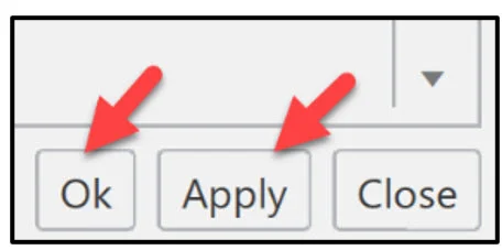
Click Apply. Click OK from the Preference dialog box.
The Assistant
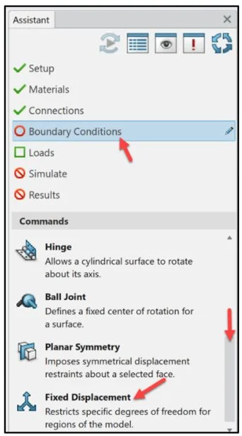
Use the Assistant. The Assistant is a useful tool if you are a beginner or experienced in simulation. The Assistant helps the user understand what conditions are required for the study.
Right-click in the Graphics area.
Click Assistant.
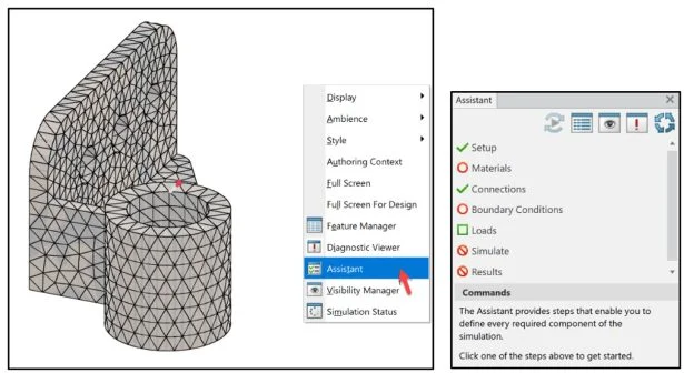
The Assistant dialog box is displayed. Setup displays a green check mark. Setup specifies the basic conditions for the simulation. The Linear Structural Validation App provides default values for each setting.
Material
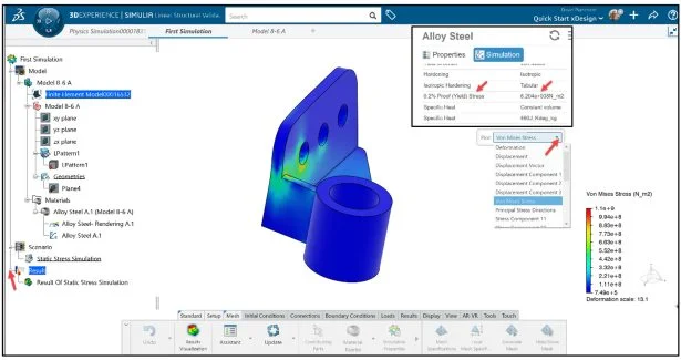
Add a Linear material. Enter Alloy Steel.
Click Materials from the Assistant dialog box.
Drag the slider downward to view the Material Palette.
Click Material Palette from the Assistant dialog box.
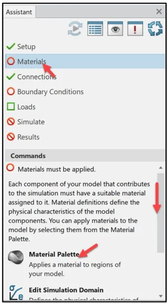
The Material Palette dialog box is displayed.
Enter Alloy Steel in the Filter Search box. View the results. Your material library maybe different than illustrated.
Click Alloy Steel under the Steel column.
Click the Simulation tab. The material definition in a FEA simulation specifies all of the relevant material properties and the proper material behavior (such as Density, Young’s Modulus, Thermal conductivity, etc.).
Return back to the Material screen.
Drag and drop Alloy Steel on the model.
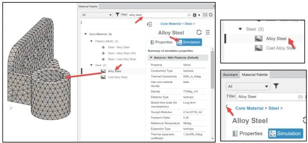
The material is applied to the model.
Click the green check mark from the Pop-up menu.
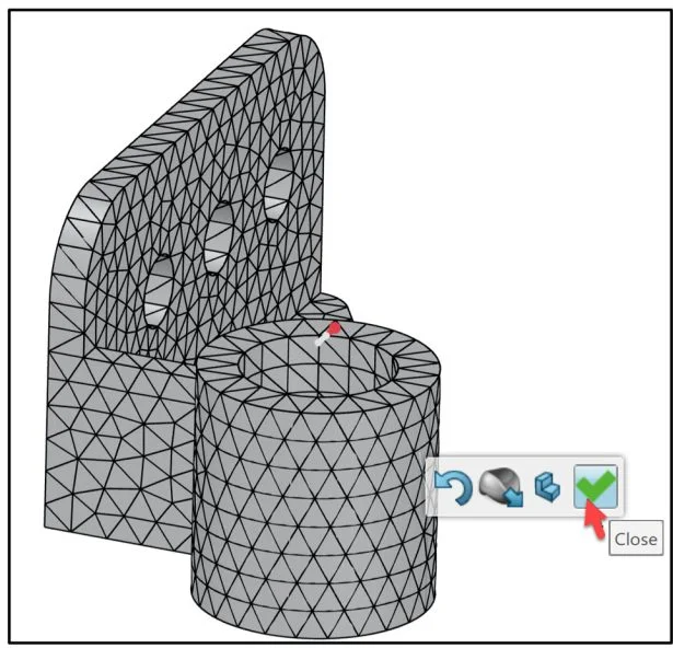
Close the Material Palette dialog box.
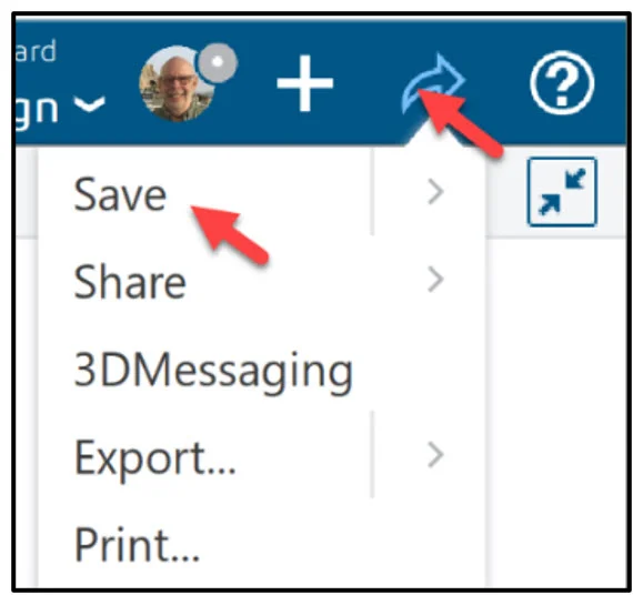
Save Study
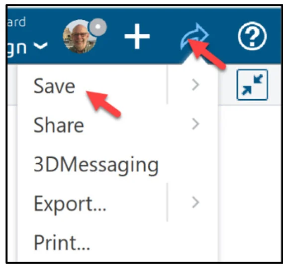
Save the Simulation study.
Click the Share icon as illustrated.
Click Save. By default, the model and Simulation study data is saved to your Collaborative space on the platform. For Simulation study data, there are two locations, either on your local machine or on the platform. By default, the Simulation study data is stored to your Collaborative space.
No Connections are required for the study. The Assistant displays a green checkmark.
Boundary Conditions
Address Boundary Conditions. Restraints are used to restrict the motion of certain surfaces in the model when loaded. In a Static Stress simulation, one or more restraints are required. Apply three restraints in the study.
Click Boundary Conditions from the Assistant dialog box.
Drag the slider downward to view Fixed Displacement.
Click Fixed Displacement.
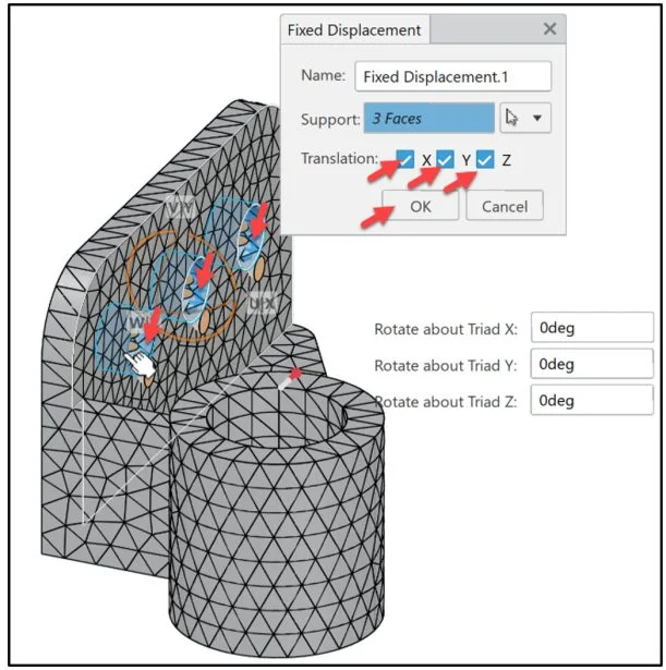
The Fixed Displacement dialog box is displayed.
Select the inside faces of the three holes. 3 Faces are displayed in the Support box.
Click the X, Y, Z Translation box. No movement in the X, Y, Z direction will occur.
Click OK from the Fixed Displacement dialog box. Boundary Conditions display a green check mark in the Assistant.
View the Simulation Study tree. The Simulation Study tree displays the object structure. The Material area displays Alloy Steel. The Scenario area displays a Static Stress Simulation.
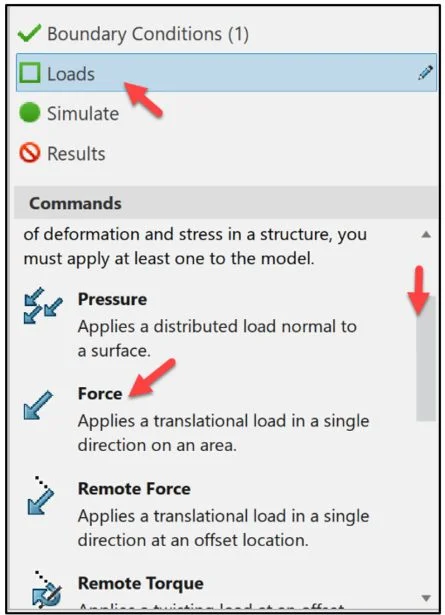
Loads
Apply a translational load (13300N Force) in a single direction on a flat face.
Click Loads from the Assistant dialog box.
Drag the slider downward to view Force.
Click Force.
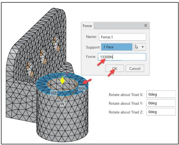
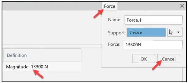
The Force dialog box is displayed. The default name is Force.1. The default unit in the Abaqus solver is Newton.
Click the top circular face of the model as illustrated. 1 Face is displayed in the Support box.
Enter 13300N for Force. The Force is pointing downwards in the Global or local z direction.
Click OK from the Force dialog box.
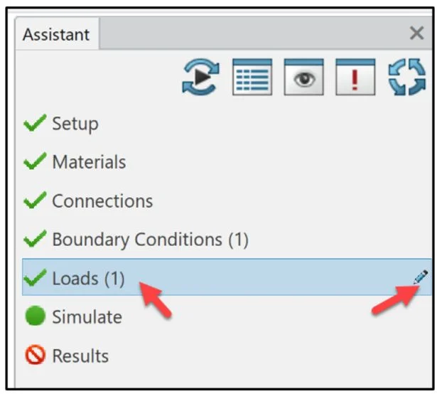
Loads (1) is created. A green check mark is displayed.
Click Loads (1) in the Assistant dialog box.
Click the edit icon.
The Feature Manager dialog box is displayed.
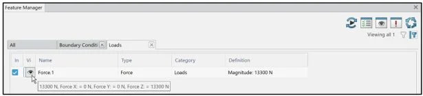
Double-click Magnitude: 13300N in the Definition column. The Force dialog box is displayed. Edit the Force if needed. Note: This will be performed in Lesson 12 Part 2.
Click Cancel.
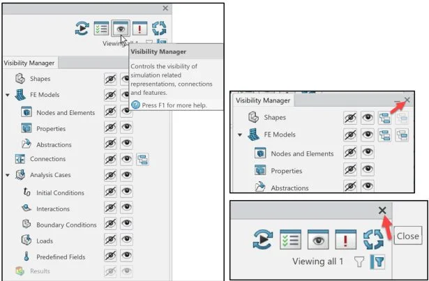
Visibility Manager
Click the Visibility Manager icon. The Visibility Manager is displayed.
View your options to Hide/Show Simulation Study objects.
Close the Visibility Manager dialog box.
Close the Feature Manager dialog box.
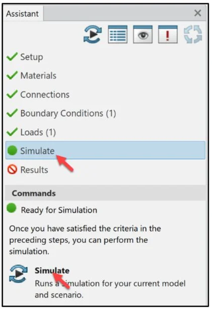
Simulate
Run the Simulation.
Click Simulate from the Assistant dialog box.
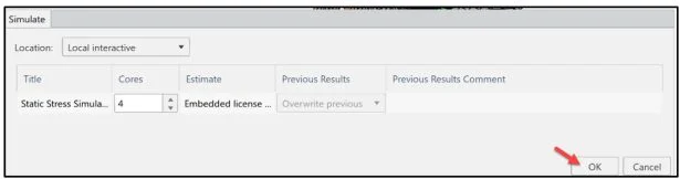
Click Simulate as illustrated to run the Linear Static Simulation.
For a new user, It is recommended to run the Simulation using Local interactive. Local interactive is set by default using an embedded license. The Simulation is executed on your computer and the user interface is locked while the Simulation is in process.
Up to 4 physical cores are supported when using an Educational license.
Click OK from the Simulate dialog box.
Expand and read the Warnings.
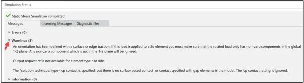
Close the Simulation Status dialog box.
Click Close.
Close the Assistant dialog box.
Results Von Mises Stress Plot
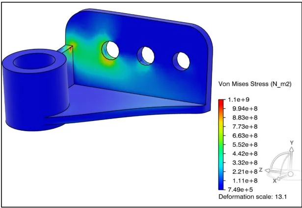
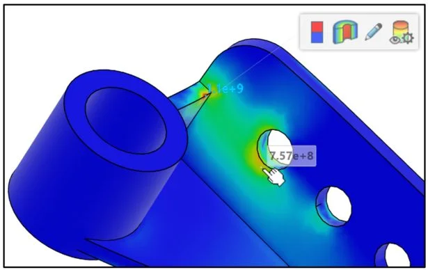
Analyze the simulation results to understand the stress and displacement patterns that develop as the force deforms the model. The Von Mises Stress plot is displayed by default.
In this example, use the result contour plots for the Von Mises stress, Displacement, and Factor of Safety (FOS). Verify that the Von Mises stresses do not exceed the material’s yield strength. For most metals, the yield strength is defined as the stress point at 0.2% strain offset. For Alloy Steel this is (6.204 × 10⁸N/m2).The maximum Von Mises stress (1.1 × 10⁹N/m2) is above the material’s yield strength of (6.204 × 10⁸N/m2). Basics of Stress Limits for 3DEXPERIENCE – YouTube.
The mouse cursor automatically acts as a probe.
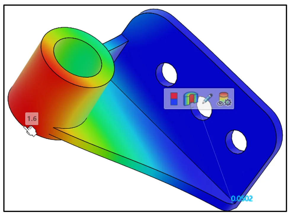
Rotate the part to view the highest stress area.
Click a point on the model as illustrated. View the Von Mises Stress at that point. A Pop-up menu is displayed. Note: to deselect the displayed point, click in the Graphics area.
Click the Show Min/Max Values icon in the Pop-up menu.
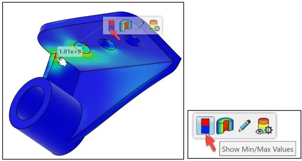
View the results. The maximum stress occurs at the corner as illustrated. The maximum Von Mises stress (1.1 × 10⁹N/m2) is above the material’s yield strength of (6.204 × 10⁸N/m2).
Click the Hide Max or Min values and close icon.
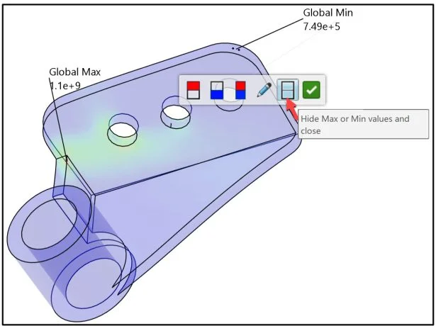
The bolt hole closest to the maximum stress also experiences a high amount of stress compared to other regions of the model. When a part sustains high stress values that exceed the material’s yield strength, you need to validate that the part is safe from material failure.
Results Displacement Plot
Create a Displacement contour plot. Note: In SOLIDWORKS Simulation the URES Resultant Displacement and the Displacement in 3DEXPERIENCE Simulation represents the same displacement components. Displacement Component 1, 2 and 3 in 3DEXPERIENCE Simulation represents the same displacement components as UX, UY and UZ in SOLIDWORKS Simulation.
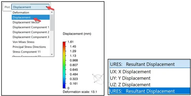
The maximum displacement occurs at the bottom of the cylindrical feature. There is a relatively small amount (0.0502mm) of deformation on one side of the base.

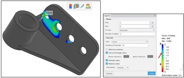
Results Factor of Safety Plot
Review the Factor of Safety (FOS) contour plot to identify the critical regions of the model.
The FOS plot displays how close a material is to yielding. The Factor of Safety is calculated by dividing the material’s Proof (Yield) Strength by the Allowable stress.
Create a Factor of Safety (FOS) contour plot.
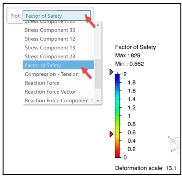
The FOS plot has a maximum limit of 2 by default. Regions of the model with a FOS larger than 2 are shown in gray.
Regions of the model with a FOS less than 1, develop stresses above the material’s yield strength under the current loading conditions.
The smallest factors of safety occur in the localized regions where the highest Von Mises stresses occur.
Note: To modify the max value of the FOS plot, double-click the plot legend, and enter a value.
Save and Close
Save the model and Simulation study.
Click the Share icon as illustrated.
Click Save.
Close the Simulation study.
Click Close on the First Simulation A tab.
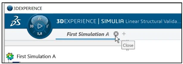
The lesson is finished.
In Analysis Lesson 3: SOLIDWORKS and 3DEXPERIENCE Simulation Linear Structural Part2, modify the Simulation Study and create a Simulation report.
More to Explore
3DEXPERIENCE Communities:
Academic Community: After you create a 3DEXPERIENCE ID, Educators, can get more information on SOLIDWORKS and the 3DEXPERIENCE Platform. Request to join the 3DEXPERIENCE Academic Community for free at go.3ds.com/academiccommunity.
Student Community: Students, join the student community for free at go.3ds.com/studentcommunity. Check out great posts on Mechanism Mondays, FEA Fridays, Solid Saturdays (animations), Formula Student and Formula SAE exercises.
Additional tutorials and lessons:
My SolidWorks and 3DEXPERIENCE Edu Space.
Additional Lessons in 3DEXPERIENCE Simulation Series:
Analysis Lesson 1: SOLIDWORKS and 3DEXPERIENCE Simulation for Diving Board
Additional Lessons in this series on 3DEXPERIENCE Works:
3DEXPERIENCE Works Lesson 1: Getting Started with SOLIDWORKS and the Platform
3DEXPERIENCE Works Lesson 2: SOLIDWORKS and Save and Revision
3DEXPERIENCE Works Lesson 3: SOLIDWORKS and Bookmarks, Share and Delete
3DEXPERIENCE Works Lesson 4: SOLIDWORKS and Lifecycle Maturity States
3DEXPERIENCE Works Lesson 5: SOLIDWORKS, Collaborative Space and Bookmarks
3DEXPERIENCE Works Lesson 6: SOLIDWORKS with Search Tools
3DEXPERIENCE Works Lesson 7: SOLIDWORKS with 3DPlay
3DEXPERIENCE Works Lesson 8: SOLIDWORKS with 3DDrive
3DEXPERIENCE Works Lesson 9: SOLIDWORKS and 3DSWYM
3DEXPERIENCEWorks Lesson 10: SOLIDWORKS and 3DEXPERIENCE Simulation
Additional Lessons in this series on SOLIDWORKS xDesign:
SOLIDWORKS xDesign Lesson #1: Getting Started
SOLIDWORKS xDesign Lesson #2: Mouse Control and Collaborative Space
SOLIDWORKS xDesign Lesson #3: Sketch Planes
SOLIDWORKS xDesign Lesson #4: Create A Dashboard
SOLIDWORKS xDesign Lesson #5: Views and Orientations
SOLIDWORKS xDesign Lesson #6: Importing Files and Using Bookmarks
SOLIDWORKS xDesign Lesson #7: Assemblies
SOLIDWORKS xDesign Lesson #8: 4Bar Linkage and Kinematics
SOLIDWORKS xDesign Lesson #9: External References and Copy with Mates
SOLIDWORKS xDesign Lesson #10: Sketching, Constraints and Dimensions
SOLIDWORKS xDesign Lesson #11: Sketch Based and Applied Features
Design well, Marie