
After teaching 1000’s of students and writing about SOLIDWORKS for over 25 years, David Planchard, emeritus WPI, is exploring SOLIDWORKS desktop and the integrated 3DEXPERIENCE Platform. Through the 3DEXPERIENCE Works Lesson series, David helps educators understand the 3DEXPERIENCE Engineer, Fluid Scenario Creation App (CFD) with simple examples and industry practices. The Platform offers are available thru your Education Partner (VAR).
Dassault Systèmes owns SOLIDWORKS and various simulation software packages. Simulation packages range from SOLIDWORKS Simulation, CATIA Analysis, Abaqus and many others. All of them are under the SIMULIA family.
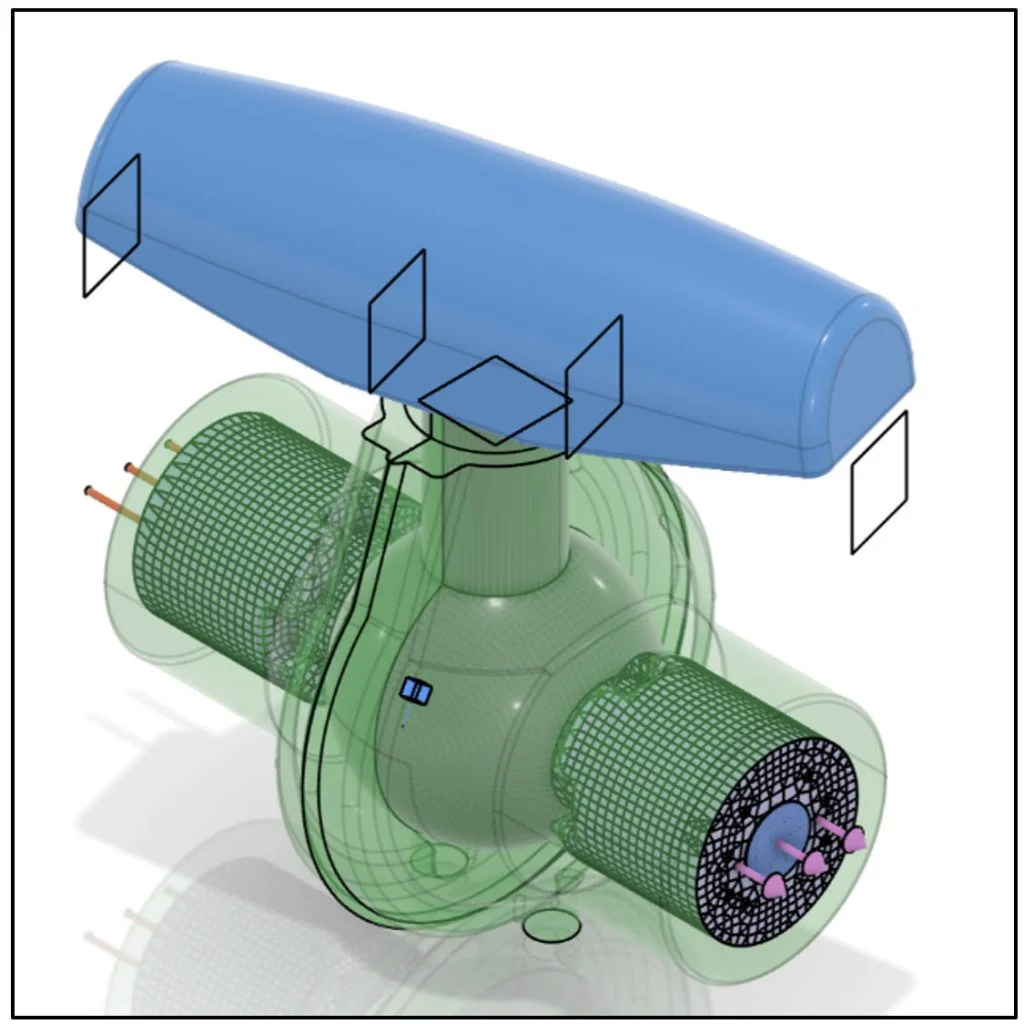
In this lesson, learn the proper workflow to upload a SOLIDWORKS assembly to the 3DEXPERIENCE platform. Create and perform a simple internal flow simulation on a ball valve using the Fluid Scenario Creation App. The Fluid Scenario Creation App provides the ability to perform an analysis of both internal and external flows.
Open a SOLIDWORKS assembly that has not been saved to the 3DEXPERIENCE platform. Upload the assembly to the 3DEXPERIENCE platform. Save the assembly in your Collaborative space. Use an existing Bookmark. Return to your SOLIDWORKS desktop. Lock the assembly and reference components.
Launch the Fluid Scenario Creation App. Use the Assistant to create an internal flow simulation that models the mechanical forces and dynamics of steady state fluid flow. Define a fluid region internal to the model. Define the fluid (water). Specify the physics of the flow. Create a Hex-dominant mesh for the fluid region.
Apply boundary conditions (inlet/outlet). Create output requests to collect pressure, flow velocity and mass flow results.
Run the Simulation study. Use the Physics Results Explorer App. Save the Physics Simulation study. Close the simulation study. Save the Ball valve in SOLIDWORKS. Close the active session of SOLIDWORKS.
Getting Started
Before we start, there are a few items that you need to know.
In this lesson, use your default Collaborative space. An internet connection is required. A 3DEXPERIENCE ID is required.
The Flow Simulation lesson provides a foundation to users who are new to using simulation to solve real-world engineering and design problems. You should have a basic understanding of flow, pressure, velocity and the Computational Fluid Dynamics (CFD) method.
3DEXPERIENCE Launcher needs to be installed. 3DEXPERIENCE Works Lesson 1: Getting Started with SOLIDWORKS and the Platform.
The 3DEXPERIENCE platform is browser driven. Your existing cookies and cache determine what you will see on your computer desktop or during a SOLIDWORKS login. A full installation of SOLIDWORKS 2019 SP0 or later is required.
Start a SOLIDWORKS session from your desktop.
Double-click the SOLIDWORKS icon.
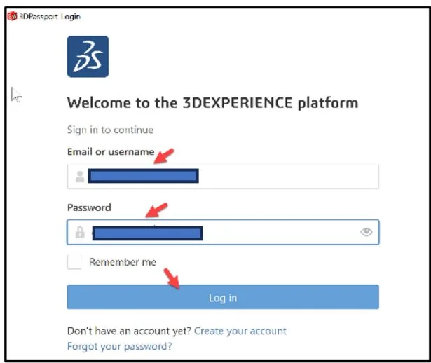
View the illustration below. Depending on your system setup, cookies, and cache, it will be different. Read the provided information.
Input the requested data.
Click Accept All.
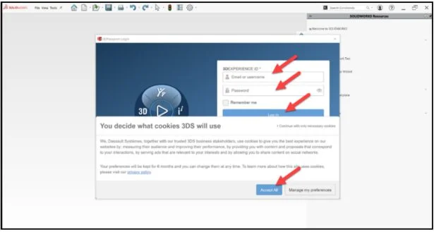
The Welcome – SOLIDWORKS dialog box is displayed.
You are logged into the 3DEXPERIENCE platform.
Close the Welcome dialog box.
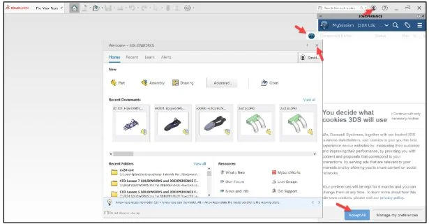
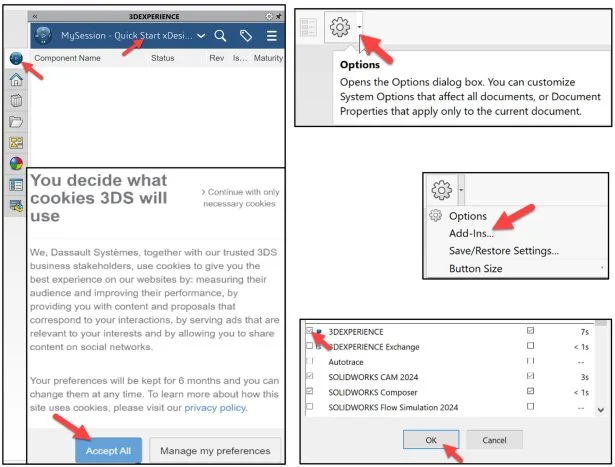
Click the 3DEXPERIENCE icon in the Task Pane. The MySession panel is displayed. This displays the two-way communication between SOLIDWORKS running on your desktop and the 3DEXPERIENCE platform running in the cloud.
In this lesson, I’m using a Collaborative space named Quick Start xDesign.
Note: If you do not see the 3DEXPERIENCE icon, click the Options drop-down arrow, click Add-Ins, check the 3DEXPERIENCE box, click OK, from the SOLIDWORKS Main menu.
Click Accept All if needed.
SOLIDWORKS Part: Ball valve
Download the SOLIDWORKS Ball valve assembly to follow along with this lesson. Note: This model is taken from the SOLIDWORKS FloXpress tutorial.
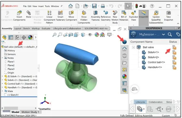
Open the Ball valve assembly that not been previously uploaded or saved to the 3DEXPERIENCE platform. Note: The Control Ball is set at 165 degrees from the Front Plane of the assembly.
Expand the Task Pane bar. The MySession panel displays a tree view of the active file and a list of commands that can be accessed through the Action bar and context menu.
Save from SOLIDWORKS to Platform
The orange save Status icon for the Ball valve assembly and reference components informs you that the local files on your computer have not been saved to the platform. Save the assembly and reference components to the 3DEXPERIENCE platform.
Click Save Active Window from the Lifecycle tab in the Action bar.
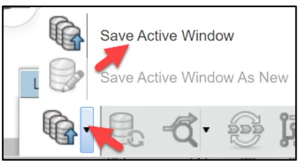
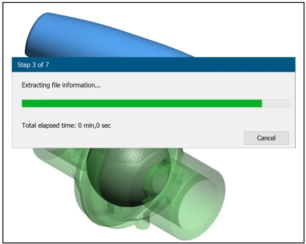
The files are temporarily being saved to a local cache area. The platform is checking for out of date components, modified components from the last save to the platform, different revisions, missing components, etc.
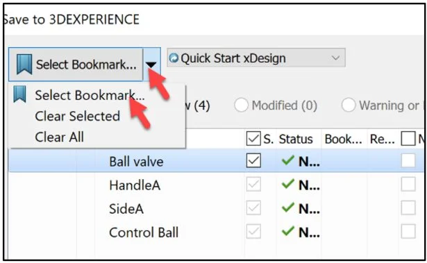
The Save to 3DEXPERIENCE dialog box is displayed. Product lifecycle management (PLM) attributes are displayed. The PLM attributes include: Bookmark locations, Selected Collaborative space, Owner, Title, Saved Status (3DEXPERIENCE), Revision, Maturity Lifecycle State and Collaborative Space name.
Bookmark
Save the assembly and the reference components. Use your existing Collaborative space. Use an existing Bookmark. Note: If needed review 3DEXPERIENCE Works Lesson 3: SOLIDWORKS Bookmarks, Share and Delete. Use Bookmarks (links) to delete entire groups of data or just a single file. For assemblies within the Bookmark folder, there is an option to delete the entire structure of the assembly and all reference components.
Click the Select Bookmark down arrow.
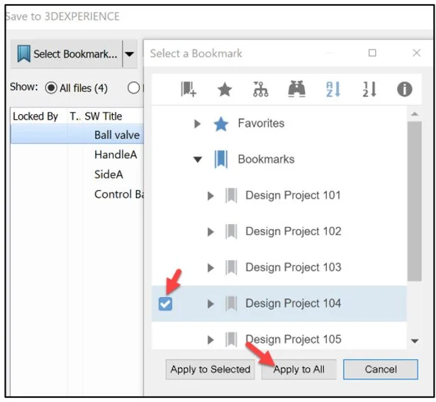
Click Select Bookmark. The Select a Bookmark dialog box is displayed.
In the below example, I selected Design Project 104 as my bookmark.
Click Apply to All from the Select a Bookmark dialog box.
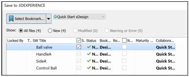
Click Save from the Save to 3DEXPERIENCE dialog box.
The assembly and reference components are directly loaded into your Collaborative space and Bookmarked on the 3DEXPERIENCE platform. You are returned back into your SOLIDWORKS desktop session.
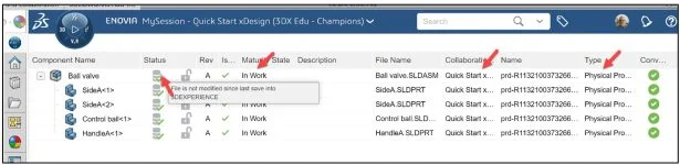
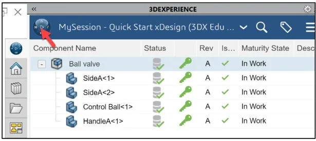
View the Status column in the updated MySession panel. The Status icon displays a green check mark. This means that the current file on your SOLIDWORKS desktop is updated and saved to the platform. The default Revision is A. The Maturity State is “In Work”. This is the default Lifecycle state after you saved the model to the 3DEXPERIENCE platform.
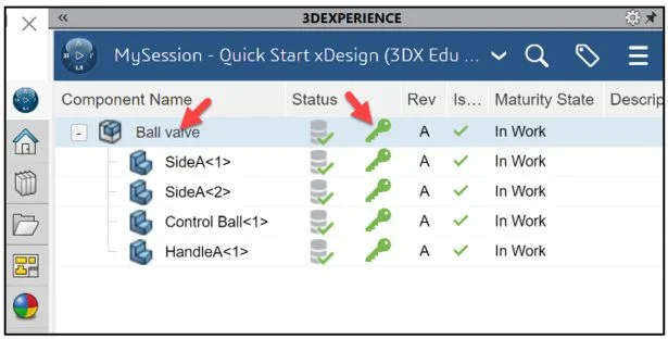
Lock the assembly and reference components in the MySession panel. This prevents anyone in making a change to them. The Lock icon is displayed.
Right-click the assembly and each component. Click Lock. The assembly and reference components are locked.
Select the Ball valve assembly from the MySession panel.
Fluid Scenario Creation App
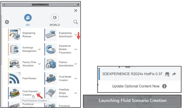
Click the center of the Compass. Use the Fluid Scenario Creation App. Think of this App as the SOLIDWORKS Flow Simulation Add-in inside of SOLIDWORKS. Most of the 3DEXPERIENCE Apps run in your web browser. 3DEXPERIENCE Simulation Apps perform a small installation on your windows machine. Both types of Apps are linked to your PLM data on the platform.
Drag the slider downward to view the Fluid Scenario Creation App.
Launch the Fluid Scenario Creation App. If this is your first time using a 3DEXPERIENCE Simulation App, or an update is available, download the needed App information on your computer. It is recommend to restart your SOLIDWORKS session.
This can take 10 – 15 seconds.
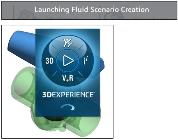
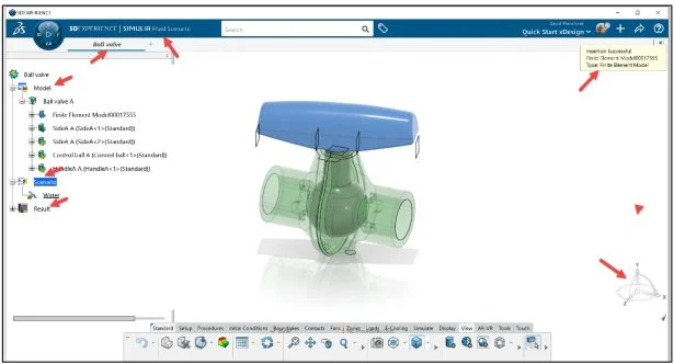
The 3DEXPERIENCE | SIMULIA Fluid Scenario Creation App is displayed.
Simulation Initialization
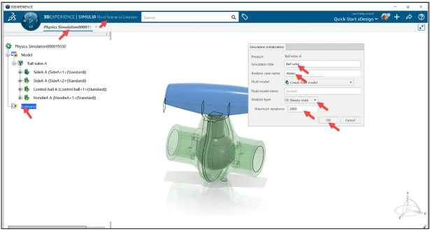
The Simulation Initialization dialog box is displayed.
Enter Ball valve for Simulation title.
Enter Water for Analysis case name.
Select Create fluid model for Fluid model type.
Accept the defaults. Analysis type: Steady-state.
Click OK from the Simulation Initialization dialog box.
Model and Scenario data is always stored on the 3DEXPERIENCE server in your Collaborative space. Result data may be stored on the server or in a local directory on your machine. Local data is masked, encrypted and only accessible by the owner of the data. Note: No procedures exist at this time.
Preferences and Units
Set mouse profile to SOLIDWORKS.
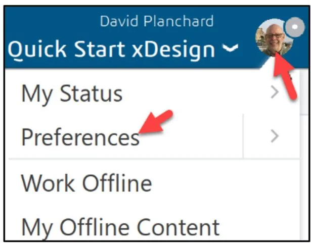
Click your profile picture (Avatar).
Click Preferences from the drop-down menu.
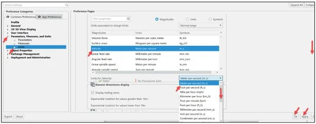
The Preference dialog box is displayed. View your options.
Click the Common Preferences tab.
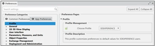
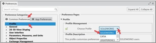
Click Profile.
Select a Profile from the Profile Management drop-down menu (SOLIDWORKS).
Check the solver unit for Velocity. A velocity of 5m/s is applied in the study.
Expand Parameters, Measures, and Units.
Click Units.
Drag the slider downward to view the Velocity. The default solver unit is Meter per second m_s.
Note: To modify the default unit, drag the inside and outside slider downward to locate the magnitude, select the magnitude, select the new unit from the drop-down menu as illustrated.
Click Apply.
Click OK from the Preferences dialog box.
Save Simulation Data
Save the Simulation study.
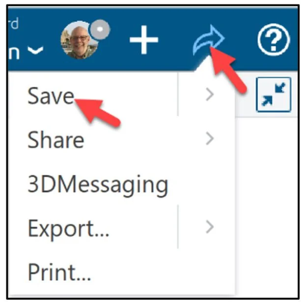
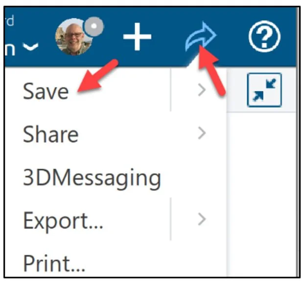
Click the Share icon as illustrated.
Click Save. By default, the model and Simulation study data are saved to your Collaborative space on the platform. For Simulation study data, there are two locations, either on your local machine or on the platform. By default, the Simulation study data is stored to your Collaborative space.
Using the Assistant
Define the Model Setup. Apply a material. The Material Definition App enables you to define materials, including their Simulation properties.
Define the region where the flow occurs.
Create an internal fluid domain inside the Ball valve assembly. A fluid domain is a finite volume consisting of one or more fluid regions that are bounded by parts, exterior geometries and openings. Note: A flow simulation has only one fluid domain.
Display the Assistant dialog box.
Right-click in the Graphics area.
Click Assistant. The Assistant dialog box is displayed.
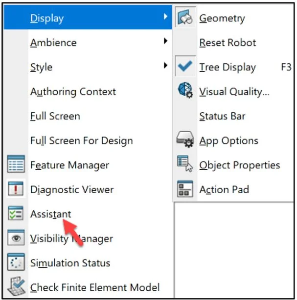
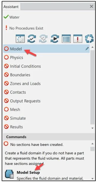
The Assistant dialog box is a helpful tool which guides the user through the Fluid Simulation process. The Assitant dialog box should be followed from top to bottom.
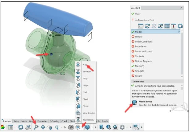
Click Model from the Assistant dialog box.
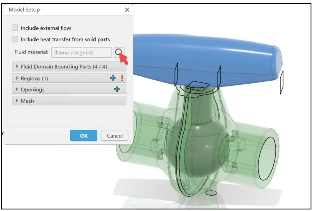
Click Model Setup from the Commands dialog box.
The Model Setup dialog box is displayed.
Apply material (water) to the fluid section associated with the fluid domain.
Click the eyeglass symbol to open the Material Palette dialog box.
Select Material and Regions
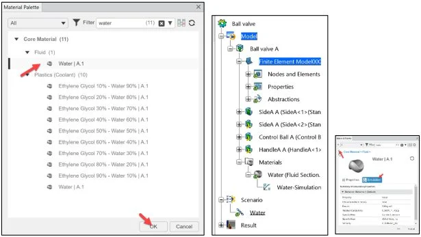
The Material Palette dialog box is displayed.
Select All.
Enter water in the Filter search box.
Select Water | A.1 under Fluid (1). View the Simulation properties.
Return to the Material Palette.
Click OK from the Material Palette dialog box if needed.
Close the Material Palette dialog box.
Material Water is added in the Simulation study tree.
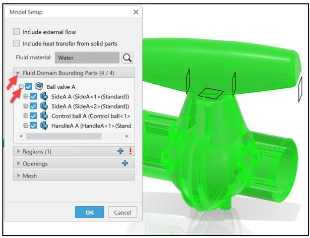
Expand the Fluid Domain Bounding Parts column as illustrated.
The four parts and the Ball valve assembly are selected by default.
Select the region (contiguous volume) that contact the fluid.
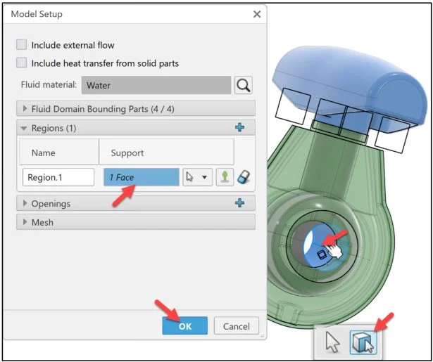
Expand the Regions (1) row as illustrated.
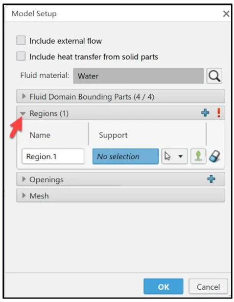
Click the Face Selection filter.
Click the inside surface of the Ball valve as illustrated. 1 Face is displayed in the Region.1 Support box.
A glyph of a blue cube with a stem is displayed on the selected surface. The cubical portion of the glyph should be immersed in what would be the fluid volume. Note: If not, select Flip Direction icon.
Click OK from the Model Setup dialog box.
Display an Isometric view in the Graphics area.
Click ISO from the View tab in the Action bar.
Click Fit All In from the View tab in the Action bar.
View the location of the blue cube in the assembly.
Click Model Setup from the Commands box.
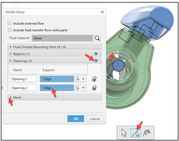
Define Openings
The Model Setup dialog box is displayed.
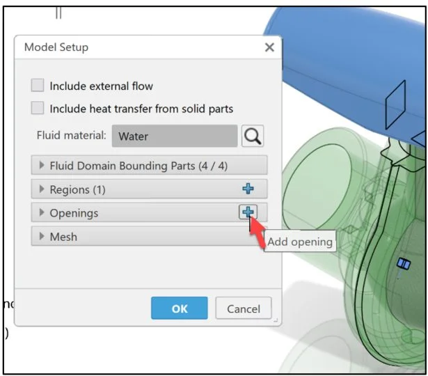
Define the openings that allow fluid to flow through the valve. An opening is a face that bounds a fluid region but for which there is no geometry.
Create the first opening.
Click the plus icon to add an opening (Inlet).
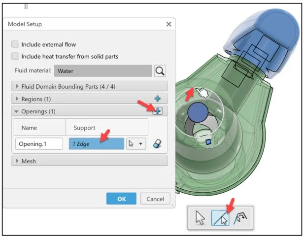
Rotate the valve to view the inlet as illustrated.
Select the Edge Selection Filter.
Click the edge of the inlet of the valve as illustrated. 1 Edge is displayed in the Support box.
Opening.1 is created and displayed in the center of the valve inlet.
Create the second opening.
Rotate the valve to view the other side (outlet) as illustrated.
Click the plus sign in the Openings (2) section.
Select the Edge Selection Filter.
Click the edge of the inlet of the valve as illustrated. 1 Edge is displayed in the Support box.
Opening.2 is created and displayed in the center of the valve inlet.
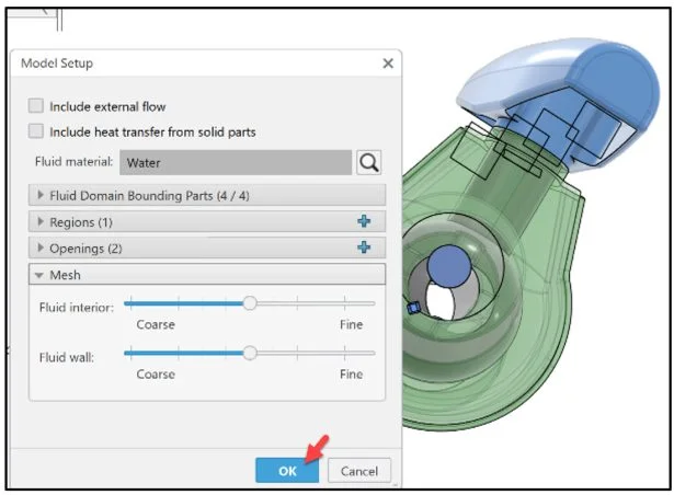
Expand the Mesh row.
View the default Mesh settings.
Click OK from the Model Setup dialog box.
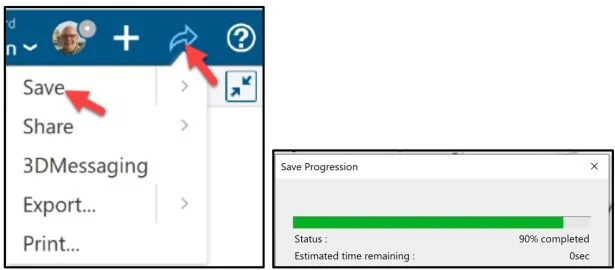
Save the Simulation study. Click the Share icon as illustrated.
Click Save.
Display an Isometric view in the Graphics area. Fit the model to the Graphics area.
Click ISO from the View tab in the Action bar. Click Fit All In from the View tab in the Action bar.
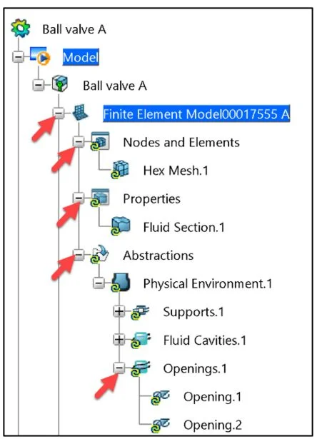
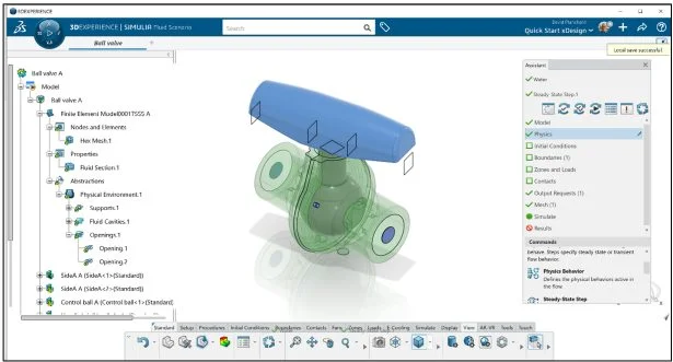
Three new items are displayed in the Simulation tree: Hex Mesh.1 (Hex-Dominant mesh) under the Nodes and Elements. Fluid Section.1 (fluid region for the Ball valve) under the Properties node. Physical Environment.1 (surface definition) under the Abstraction node.
Physics Behavior
Specify the Physics behavior of the water flowing through the Ball valve. Fluid flow physics behavior is based on various environmental effects and the application of fluid dynamics theories.
Click Physics from the Assistant dialog box.
Click Physics Behavior from the Commands box.
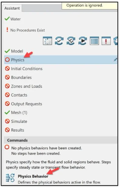
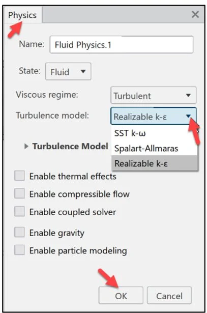
The Physics dialog box is displayed. View your options.
Accept the default name: Fluid Physics.1.
Accept the default State: Fluid.
Select Realizable k-ε from the Turbulence model drop-down menu. This model is appropriate for internal fluid flow scenarios. Note: Realizable k-ε turbulence model is one of the common models used in CFD to simulate mean flow characteristics for turbulent flow conditions.
Click OK.
View the results.
Steady State Step
Edit the parameters of the current step.
Click Edit Current Step from the Commands box.
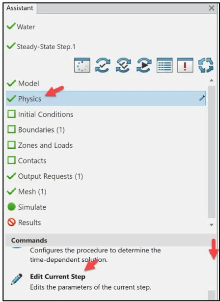
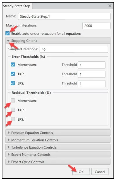
The Steady-State Step.1 dialog box is displayed. Steady-state flow is the condition where the fluid properties at any single point in the system do not change over time.
Select the Enable auto under-relaxation for all equations box. This option gradually converges the turbulence equations to the error thresholds that you specify in the Stopping Criteria section.
Expand the Stopping Criteria section.
Clear all check boxes under Residual Thresholds (%).
Click OK from the Steady-State Step dialog box.
Velocity and Pressure
Apply an Inlet flow condition. The valve has two openings (Opening.1, Opening.2). Apply a velocity condition of 5m/s at the inlet (Opening.1).
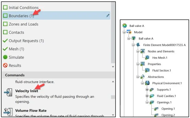
Click Boundaries from the Assistant dialog box.
Click Velocity Inlet from the Commands box.
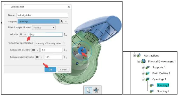
The Velocity Inlet dialog box is displayed.
Rotate the valve to view the inlet.
Select Opening.1 for Support. Note: You can select Opening.1 either by clicking its blue circular glyph in the Graphics area or by clicking its name under the Abstractions node in the study tree.
Enter 5m_s for Velocity.
Click OK from the Velocity Inlet dialog box.
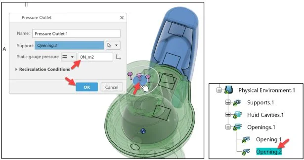
Apply an Outlet flow condition. The valve has two openings (Opening.1, Opening.2). Apply a pressure condition of 0N/m2 at the outlet (Opening.2) of the Duck.
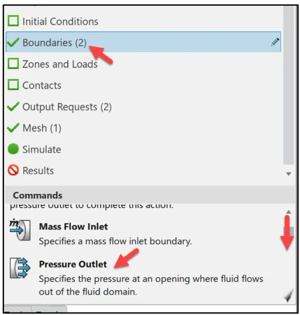
Click Boundaries from the Assistant dialog box.
Click Pressure Outlet from the Commands box.
The Pressure Outlet dialog box is displayed.
Rotate the valve to view the outlet.
Select Opening.2 for Support. Note: You can select Opening.2 either by clicking its blue circular glyph in the Graphics area or by clicking its name under the Abstractions node in the study tree.
Enter 0N_m2 for Static gauge pressure.
Click OK from the Pressure Outlet dialog box.
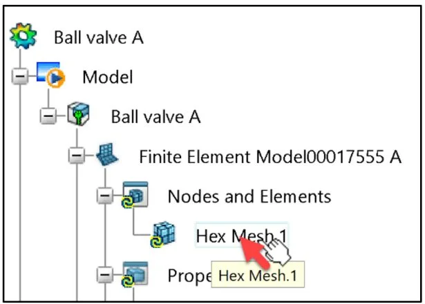
Hex Mesh
Customize the hex-dominant mesh for the fluid region.
Double-click Hex Mesh.1 from the Simulation study tree.
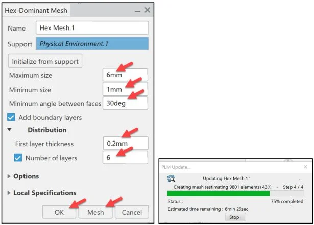
The Hex-Dominant Mesh dialog box is displayed. Currently, the Educational version of Flow Simulation has a maximum allowable node count of 1million nodes.
Enter 6mm for Maximum size.
Enter 1mm for Minimum size.
Enter 30deg for Minimum angle between faces.
Enter .2mm for First lay thickness.
Click Mesh.
Click OK from the Hex-Dominant Mesh dialog box.

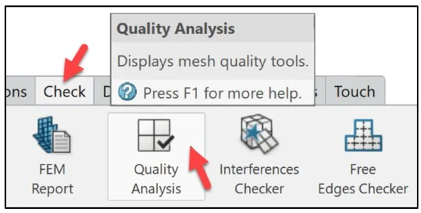
Quality Analysis
Utilize the Quality Analysis tool to view the number of nodes used and that you did not exceed the node limit.
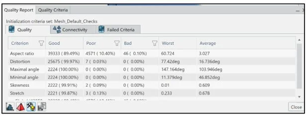
Click Quality Analysis from the Check tab in the Action Bar.
View the result under the default Quality tab. Note: Your result may vary by 1%.
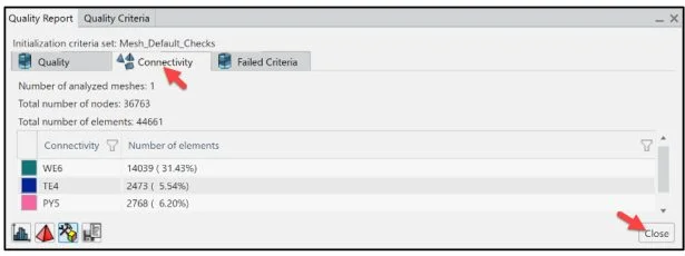
Click the Connectivity tab. View the number of used nodes.
Click Close.
Output Requests and Results
Create output requests to collect pressure, flow velocity and mass flow results.
The Physics Results Explorer App automatically creates an output request for the model when your create a Simulation study. By modifying the output request, you can filter the volume of data produced during a Simulation. You can also create output requests to collect pertinent variable data for particular supports.
In this lesson, create two output requests. The first output request is for the inlet pressure and mass flow results. The second output request is for the outlet flow velocity and mass flow results. Use this information to confirm that the Simulation converged properly and to analyze the valve’s performance.
Create the first output request.
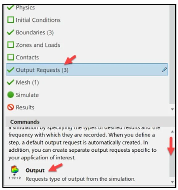
Click Output Requests from the Assistant dialog box.
Click Output from the Commands box.
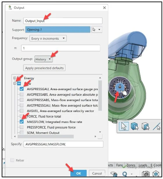
The Output dialog box is displayed.
Rotate the Ball valve to view the inlet.
Enter name: Output_Input.
Click Opening.1 (inlet) from the Graphics area as illustrated. Opening.1 is displayed in the Support box.
Select History from the Output group drop-down menu. Note: You can create two types of sensors to display different types of data: Field sensors and History sensors. Depending on the analysis case type you simulate, some Apps automatically create a set of field and history sensors by default. Default sensors streamline your workflow so you can quicly analyze your simulation results.
Expand Flow.
Click AVGPRESSGAU, Area-average surface gauge pressure.
Click MASSFLOW, Integrated mass flow rate.
Click OK from the Output dialog box.
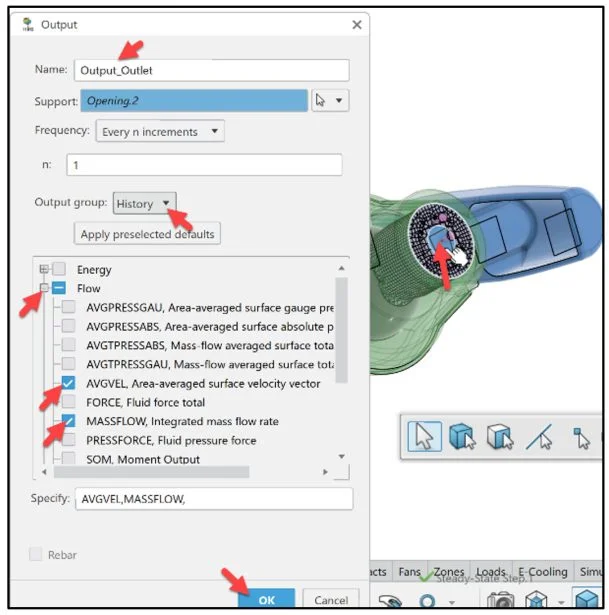
Create the second output request.
Click Output from the Commands box.
Rotate the valve to view the outlet.
Enter name: Output_Outlet.
Click Opening.2 (outlet) from the Graphics area as illustrated. Opening.2 is displayed in the Support box.
Select History from the Output group drop-down menu.
Expand Flow.
Click AVGVEL, Area averaged surface velocity vector.
Click MASSFLOW, Integrated mass flow rate.
Click OK from the Output dialog box.
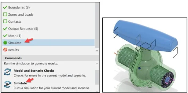
Simulate
Run the Simulation.
Click Simulate from the Assistant dialog box.
Click Simulate from the Commands box.
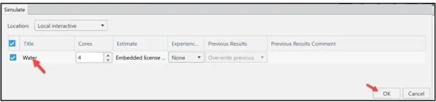
The Simulate dialog box is displayed. It is recommended to run the Simulation using Local interactive. Local interactive is set by default using an embedded license. The Simulation is executed on your computer and the user interface is locked while the Simulation is in process.
With an Educational license, up to 4 physical cores are supported. Overwrite previous is selected by default.
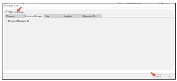
Click OK from the Simulate dialog box. Run time is approximately 1 minute.
Click Close from the Simulation Status dialog box.
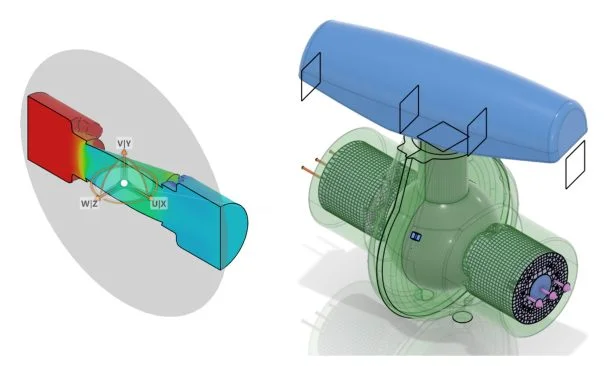
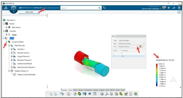
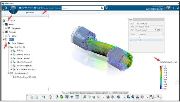
The Gauge Pressure.1 contour plot is displayed. Note: The Control Ball is set at 165 degrees from the Front Plane of the assembly
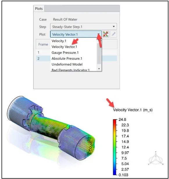
Display the Velocity Vector.1 contour plot. View the results.
The mouse cursor automatically acts as a probe.
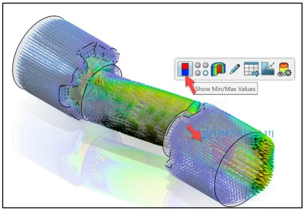
Click a point on the model as illustrated. View the Velocity Vector at that point. A Pop-up menu is displayed. Note: to deselect the displayed point, click in the Graphics area.
Click the Show Min/Max Values icon.
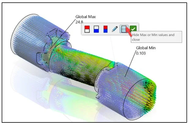
View the results.
Click the Hide Max or Min values and close icon.
Save the Physics Simulation Study
Save the Physics Simulation study (Model, Scenario and Results).
Click the Share icon as illustrated.
Click Save.
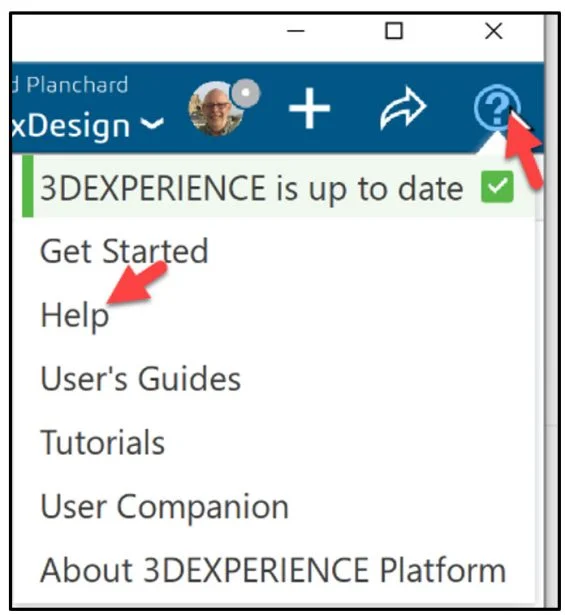
Note: To locate addition information about an active dialog box, pop-up menu or contour plot, click the Help icon as illustrated. The User Assistance is displayed.
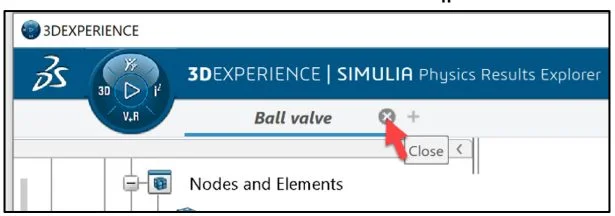
Close the Ball valve Physics Simulation study.
Click Close on the Ball valve tab.
Return to the active SOLIDWORKS session.
Save the Ball valve assembly in SOLIDWORKS.
Close the SOLIDWORKS Session.
The lesson is finished.
In Lesson 2 Part 2, start a SOLIDWORKS session. Connect to the 3DEXPERIENCE platform. Utilize the 3DSpace widget from the MySession panel in the SOLIDWORKS Task Pane.
Your 3DEXPERIENCE | 3DDashboard is displayed. Locate the Physics Simulation study named Ball valve in the saved Collaborative space. Use the sort by last or search method.
Launch the Fluid Scenario Creation App. Open the Ball valve Physics Simulation study. View the last displayed contour plot. Investigate Help tools.
Apply a section cut. Add streamlines to illustrate flow through the valve.
Save the Physics Simulation study. Close the study. Close the SOLIDWORKS session.
Community
Academic Community: After you create a 3DEXPERIENCE ID, Educators, can get more information on xDesign and SOLIDWORKS. Request to join the 3DEXPERIENCE Academic Community for free at go.3ds.com/academiccommunity.
Student Community: Students, join the student community for free at go.3ds.com/studentcommunity. Check out great posts on Mechanism Mondays, FEA Fridays, Solid Saturdays (animations), Formula Student and Formula SAE exercises.
SIMULIA Community: Students and Educations, join the SIMULIA community to learn the latest in simulation technology with the Abaqus solver, CST Studio Suite for Electro-magnetics, Antenna Magus and more.
SOLIDWORKS Community: Connect with the SOLIDWORKS community with our SOLIDWORKS User Forum, SOLIDWORKS User Groups, news and info,
SIMULIA Simulation Technology
Additional Lessons in 3DEXPERIENCE Simulation Structural Analysis:
Analysis Lesson 1: SOLIDWORKS and 3DEXPERIENCE Simulation for Diving Board
Analysis Lesson 2: SOLIDWORKS and 3DEXPERIENCE Simulation Linear Structural Validation Part 1
Analysis Lesson 3: SOLIDWORKS and 3DEXPERIENCE Simulation Linear Structural Validation Part 2
Analysis Lesson 4: SOLIDWORKS and 3DEXPERIENCE Simulation Linear Structural Validation for Assembly
Analysis Lesson 5: SOLIDWORKS and 3DEXPERIENCE Simulation Structural Model Creation
From SOLIDWORKS Desktop to the 3DXPERIENCE Platform
Additional Lessons in this series on 3DEXPERIENCE Works:
3DEXPERIENCE Works Lesson 1: Getting Started with SOLIDWORKS and the Platform
3DEXPERIENCE Works Lesson 2: SOLIDWORKS and Save and Revision
3DEXPERIENCE Works Lesson 3: SOLIDWORKS and Bookmarks, Share and Delete
3DEXPERIENCE Works Lesson 4: SOLIDWORKS and Lifecycle Maturity States
3DEXPERIENCE Works Lesson 5: SOLIDWORKS, Collaborative Space and Bookmarks
3DEXPERIENCE Works Lesson 6: SOLIDWORKS with Search Tools
3DEXPERIENCE Works Lesson 7: SOLIDWORKS with 3DPlay
3DEXPERIENCE Works Lesson 8: SOLIDWORKS with 3DDrive
3DEXPERIENCE Works Lesson 9: SOLIDWORKS and 3DSWYM
3DEXPERIENCEWorks Lesson 10: SOLIDWORKS and 3DEXPERIENCE Simulation
Cloud Apps by SOLIDWORKS (100% Browser Based)
Additional Lessons in this series on SOLIDWORKS xDesign
SOLIDWORKS xDesign Lesson #1: Getting Started
SOLIDWORKS xDesign Lesson #2: Mouse Control and Collaborative Space
SOLIDWORKS xDesign Lesson #3: Sketch Planes
SOLIDWORKS xDesign Lesson #4: Create A Dashboard
SOLIDWORKS xDesign Lesson #5: Views and Orientations
SOLIDWORKS xDesign Lesson #6: Importing Files and Using Bookmarks
SOLIDWORKS xDesign Lesson #7: Assemblies
SOLIDWORKS xDesign Lesson #8: 4Bar Linkage and Kinematics
SOLIDWORKS xDesign Lesson #9: External References and Copy with Mates
SOLIDWORKS xDesign Lesson #10: Sketching, Constraints and Dimensions
SOLIDWORKS xDesign Lesson #11: Sketch Based and Applied Features
Design well, Marie