
After teaching 1000’s of students and writing about SOLIDWORKS for over 25 years, David Planchard, emeritus WPI, is exploring the 3DEXPERIENCE platform. Through the SOLIDWORKS and 3DEXPERIENCE Simulation Lesson series, David helps educators understand 3DEXPERIENCE Simulation fundamentals through simple examples.
In this lesson learn the proper workflow to upload a SOLIDWORKS part to the 3DEXPERIENCE platform and perform a Simulation study using the Structural Model Creation App.
Open a SOLIDWORKS Sheet metal part that has not been saved to the 3DEXPERIENCE platform.
Upload the SOLIDWORKS part to the 3DEXPERIENCE platform. Save the part in your Collaborative space. Use an existing Bookmark. Return to your SOLIDWORKS desktop. Lock the part.
Launch the Structural Model Creation App from the SOLIDWORKS Task Pane. Create an empty Finite Element Model (FEM) linked to the shape of the part. Apply Alloy Steel. Create a Surface Quadratic Mesh. Utilize the Shell Section tool. Define the uniform shell thickness.
Create the Simulation Scenario. Launch the Structural Scenario Creation App. Apply the created Finite Element Model (FEM). Create a Static Step.
Apply three Fixed Displacements. Apply an External load (Force) of 400N.
Run the Simulation study. Use the Physics Results Explorer App to manage results data from Simulations performed within the 3DEXPERIENCE platform.
Create three Simulation contour plots: Von Mises Stress, Factor of Safety (FOS) and Displacement.
Analyze the Simulation plots. Save the Simulation study to your Collaborative space. View the items of the Simulation study saved to your Collaborative space.
Before we start, there are a few items that you need to know.
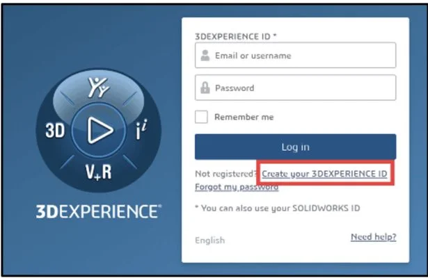
In this lesson, use your default Collaborative space. An internet connection is required. A 3DEXPERIENCE ID is required.
The Simulation lesson provides a foundation to users who are new to using simulation to solve real-word engineering and design problems. You should have a basic understanding of Stress and Finite Element Method (FEM).
Launch the 3DEXPERIENCE platform and Start SOLIDWORKS
3DEXPERIENCE Launcher needs to be installed. 3DEXPERIENCE Works Lesson 1: Getting Started with SOLIDWORKS.
The 3DEXPERIENCE platform is browser driven. Your existing cookies and cache determine what you will see on your computer desktop or during a SOLIDWORKS login. A full installation of SOLIDWORKS 2019 SP0 or later is required.
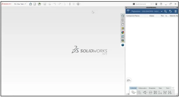
Start a SOLIDWORKS session from your desktop.
Double-click the SOLIDWORKS icon.
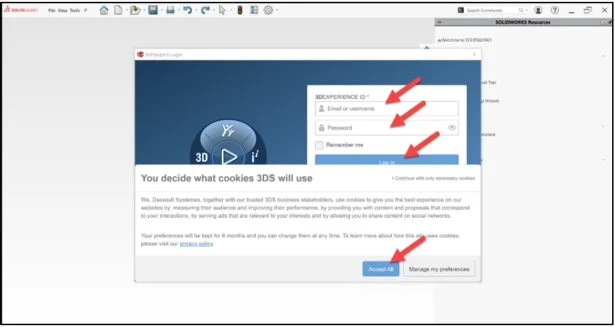
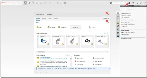
View the illustration below. Depending on your system setup, cookies, and cache, it will be different. Read the provided information.
Input the requested data.
Click Accept All.
The Welcome – SOLIDWORKS dialog box is displayed.
You are logged into the 3DEXPERIENCE platform.
Close the Welcome dialog box.
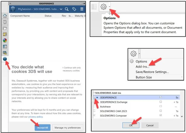
Click the 3DEXPERIENCE icon in the Task Pane. The MySession panel is displayed. This displays the two-way communication between SOLIDWORKS running on your desktop and the 3DEXPERIENCE platform running in the cloud.
In this lesson, I’m using a Collaborative space named Quick Start xDesign.
Note: If you do not see the 3DEXPERIENCE icon, click the Options drop-down arrow, click Add-Ins, check the 3DEXPERIENCE box, click OK, from the SOLIDWORKS Main menu.
Click Accept All.
Sheet metal part Model 8-4
Download the SOLIDWORKS Sheet metal part Model 8-4 to follow along with this lesson.
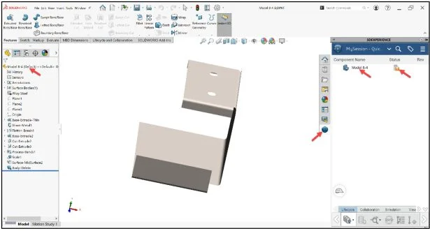
Open Model 8-4 that has not been previously uploaded or saved to the 3DEXPERIENCE platform.
Expand the Task Pane bar. The MySession panel displays a tree view of the active file and a list of commands that can be accessed through the Action bar and context menu.
The orange save Status icon for the Model 8-4 part informs you that the local file on your computer has not been saved to the platform.
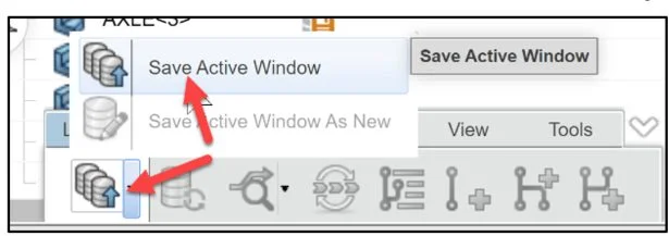
Save the part to the 3DEXPERIENCE platform.
Click Save Active Window from the Lifecycle tab in the Action bar.
The file is temporarily being saved to a local cache area. The platform is checking for out of date components, modified components from the last save to the platform, different revisions, missing components, etc.
Select a Bookmark
The Save to 3DEXPERIENCE dialog box and PLM attributes are displayed.
Save the model. Use your existing Collaborative space. Use an existing Bookmark. Note: if needed view 3DEXPERIENCE Works Lesson 3: SOLIDWORKS Bookmarks, Share and Delete.
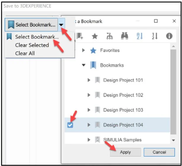
Click the Select Bookmark down-arrow.
Click Select Bookmark. The Select a Bookmark dialog box is displayed.
In the below example, I selected Design Project 104 as my bookmark.
Click Apply from the Select a Bookmark dialog box.
Click Save from the Save to 3DEXPERIENCE dialog box.
The model is directly loaded into your Collaborative space and Bookmarked on the 3DEXPERIENCE platform. You are back into your SOLIDWORKS desktop session.
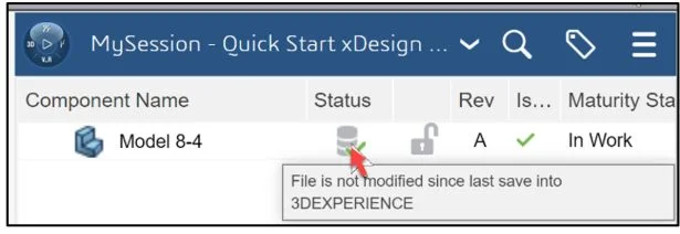
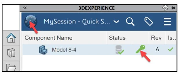
View the Status column in the updated MySession panel. The Status icon displays a green check mark. This means that the current file on your SOLIDWORKS desktop is updated and saved to the platform. The default Revision is A. The Maturity State is “In Work”. This is the default Lifecycle state after you saved the model to the 3DEXPERIENCE platform.
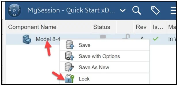
Lock the part. This prevents anyone else in making a change to it.
Right-click Model 8-4 in the MySession box.
Click Lock. The Lock icon is displayed. Model 8-4is selected.
Launch Structural Model Creation App
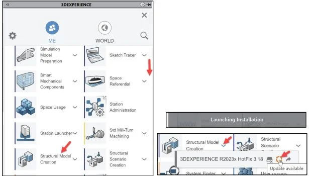
Click the center of the Compass. Launch the Structural Model Creation App. Think of this App as the SOLIDWORKS Simulation Add-in inside of SOLIDWORKS. Most of the 3DEXPERIENCE Apps run in your web browser. 3DEXPERIENCE Simulation Apps perform a small installation on your windows machine. Both types of Apps are linked to your PLM data on the platform.
Drag the slider downward to view the Structural Model Creation App.
Launch the Structural Model Creation App. Note: If this is your first time using a 3DEXPERIENCE Simulation App or an update is available, download the needed App information on your computer. It is recommended to restart your SOLIDWORKS session.
This can take 10 – 15 seconds.
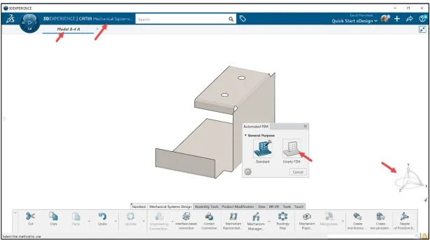
The 3DEXPERIENCE | CATIA Mechanical Systems Creation App is displayed.
Create a Empty FEM
The Automated FEM dialog box is displayed. Automated FEM is a series of methods that allows you to mesh products and assemblies. The greatest advantage of Automated FEM is that ability to mesh multiple products without the need to load all the geometry and finite element models into memory.
Click Empty FEM from the Automated FEM dialog box. This creates an empty finite element model (without creating a mesh) linked to the selected shapes.
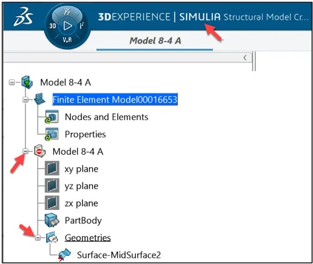
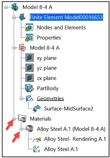
View the Simulation study tree.
Apply Material
Define Alloy Steel to the Sheet metal model.
Click the Setup tab from the Action bar.
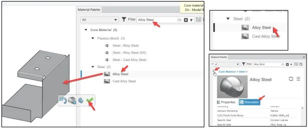
Click Material Palette as illustrated.
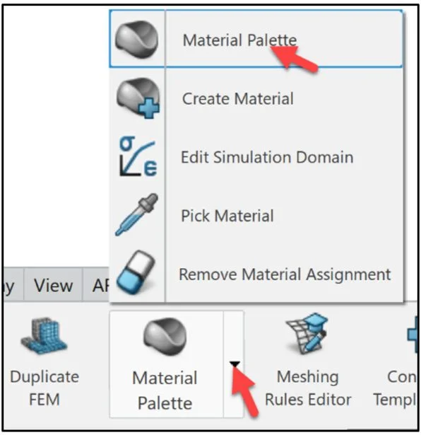
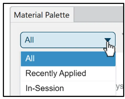
The Material Palette dialog box is displayed. The Material Palette enables you to browse from materials, research their attributes, compare them and apply them to components in the model.
Select All from the drop-down menu.
Enter Alloy Steel in the Filter Search box. View the results. Your material library maybe different than illustrated.
Click Alloy Steel under the Steel column.
Click the Simulation tab. The material definition in a FEA simulation specifies all of the relevant material properties and the proper material behavior (such as Density, Young’s Modulus, Thermal conductivity, etc.).
Return back to the Material screen.
Drag and drop Alloy Steel on the model.
The material is applied to the model.
Click the green check mark from the Pop-up menu.
Close the Material Palette dialog box.
View the updated Simulation study.
Surface Quad Mesh
Mesh the model.
Click the Mesh tab from the Action bar.
Click Surface Quad Mesh.
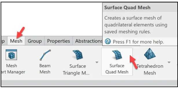
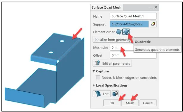
The Surface Quad Mesh dialog box is displayed.
Click the model in the Graphics area. Surface-MidSurface2 is displayed in the Support box.
Click Quadratic for Element order.
Accept the default Mesh size.
Click Mesh. Click OK. The mesh is displayed on the model.
Surface Quad Mesh.1 is displayed under the Nodes and Elements folder.
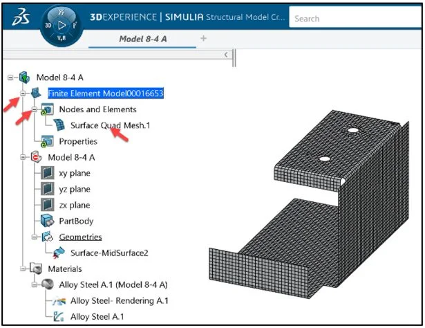
Name the default Simulation title.
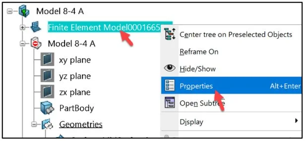
Right-click the default Simulation title (Finite Element Model#######).
Click Properties.
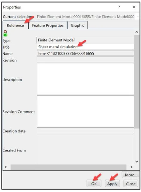
The Properties dialog box is displayed. Click the Reference tab.
Enter Sheet metal simulation in the Title box.
Click Apply.
Click OK from the Properties dialog box.
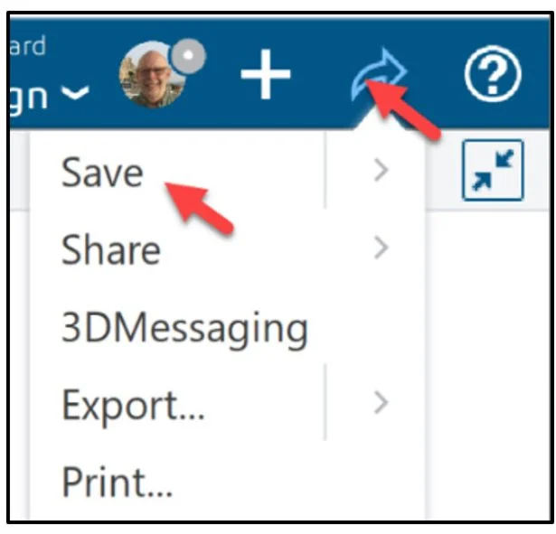
Save the Simulation study.
Click the Share icon as illustrated.
Click Save.
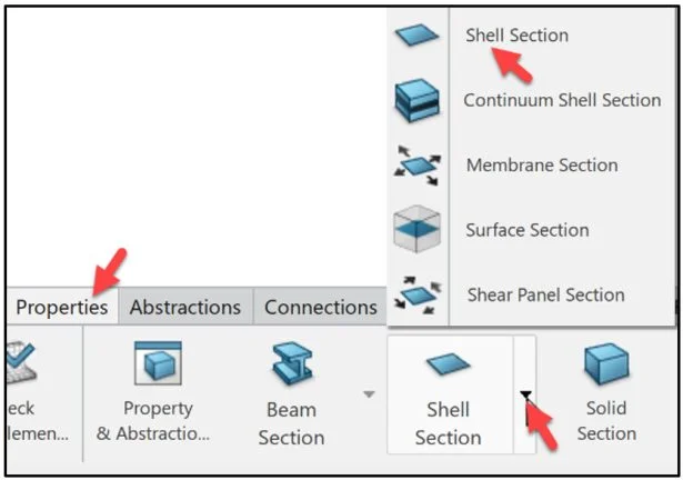
Shell Section
Define the Shell thickness. A shell section defines a structure in which one dimension (the thickness) is significantly smaller that the other two dimensions (and in which the stresses in the thickness drection are negligible.
Click the Properties tab from the Action bar.
Click Shell Section as illustrated.
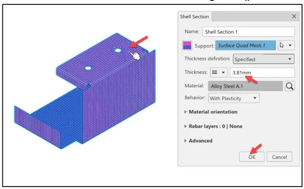
The Shell Section dialog box is displayed.
Click the model in the Graphics area as illustrated.
Enter 3.81mm for Uniform Thickness value. Accept the defaults.
Click OK from the Shell Section dialog box.
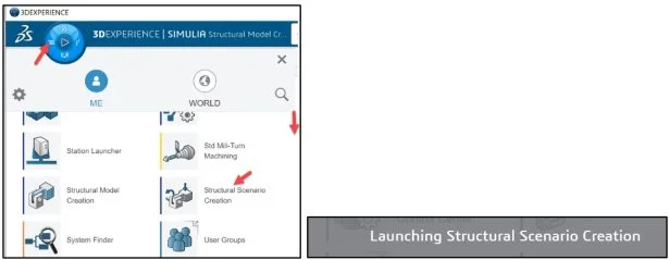
Launch Structural Scenario Creation App
Create the Simulation Scenario.
Launch the Structural Scenario Creation App.
The Simulation Initialization dialog box is displayed. Accept the default Simulation title and Analysis type.
Select the created FEM (Sheet metal simulation A) from the Finite element model drop-down menu.
Click OK from the Simulation Initialization dialog box.
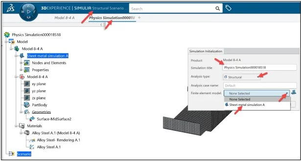
View the updated Simulation study. The Simulation study tree displays the Structural Simulation Process. Model (Geometry, Meshing (Element Family), and Property Definition). Scenario (Simulation Type, Solution Method, Element Type, Boundary Conditions, Loads and Solver). Result (Types of plots, Animations and Tools).
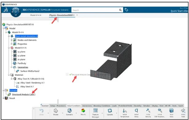
Create a Static Step
Create a Static step. A Static step performs a stress analysis of a stable problem in which inertia effects are neglected. During a Static step, a time period is assigned to the analysis. This is required for cross-references to the amplitude options, which can be used to determine the variation of loads and other externally prescribed parameters during a step.
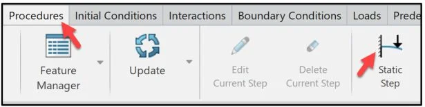
Click the Procedures tab in the Action bar.
Click Static Step.
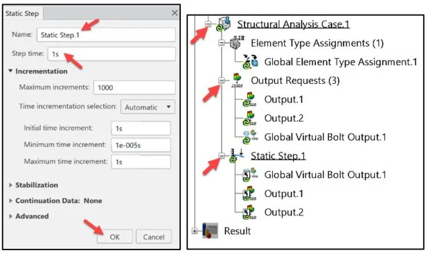
The Static Step dialog box is displayed. The default Name is Static Step.1
The Default Step time is 1s. Accept the defaults.
Click OK from the Static Step dialog box.
View the updated Simulation study tree.
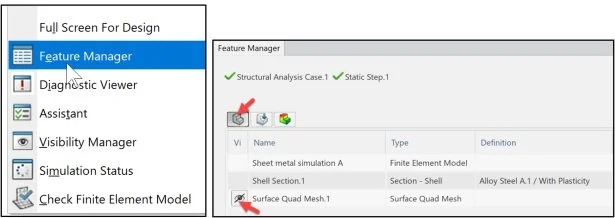
Hide the mesh. Right-click in the Graphics area.
Click Feature Manager.
Click the Model icon as illustrated.
Click the Hide Surface Quad Mesh.1 icon as illustrated.
Close the Feature Manager.
View the Assistant dialog box. Right-click in the Graphics area. Click Assistant
Apply Boundary Conditions and Loads
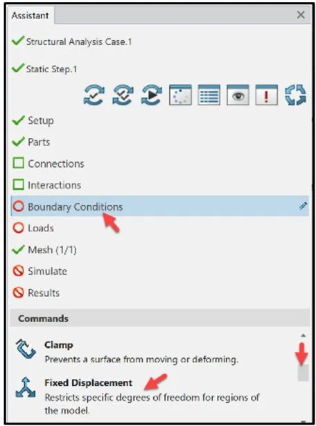
The Assistant dialog box is displayed. No Connections or Interactions are required in this study. Address Boundary Conditions. Restraints are used to restrict the motion of certain surfaces in the model when loaded.
Click Boundary Conditions in the Assistant dialog box. Drag the slider down-ward to view Fixed Displacement.
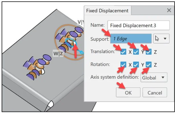
Click Fixed Displacement from the Commands box. A fix displacement lets you fix the position on the chosen geometry support by specifying that the geometry will not move in the X, Y, and/or Z-directions (for a Cartesian coordinate system).
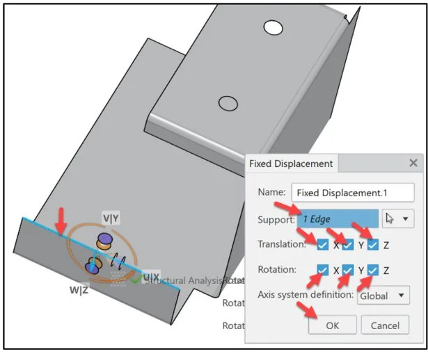
The Fixed Displacement dialog box is displayed. Accept the default name.
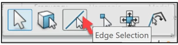
The Selection filter Pop-up menu is displayed. Click the Edge Selection icon.
Click the front top edge as illustrated. 1 Edge is displayed in the Support box.
Check X, Y, Z for Translation.
Check X, Y, Z for Rotation.
Click OK from the Fixed Displacement dialog box.
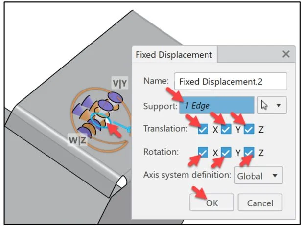
Click Fixed Displacement from the Commands box.
Select the Edge Selection icon from the Selection filter Pop-up menu.
Click the first hole edge on the top as illustrated. 1 Edge is displayed in the Support box.
Check X, Y, Z for Translation.
Check X, Y, Z for Rotation.
Click OK from the Fixed Displacement dialog box.
Click Fixed Displacement from the Commands box.
Select the Edge Selection icon from the Selection filter Pop-up menu.
Click the second hole edge on the top as illustrated. 1 Edge is displayed in the Support box.
Check X, Y, Z for Translation.
Check X, Y, Z for Rotation.
Click OK from the Fixed Displacement dialog box.
Three Fixed Displacements are displayed in the Simulation study.
Save the Simulation study.
Click the Share icon as illustrated.
Click Save.
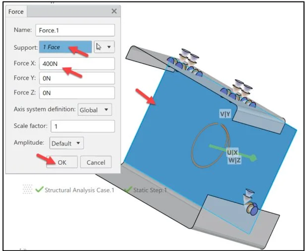
Apply an External load (Force) of 400N normal to the inside face of the model.
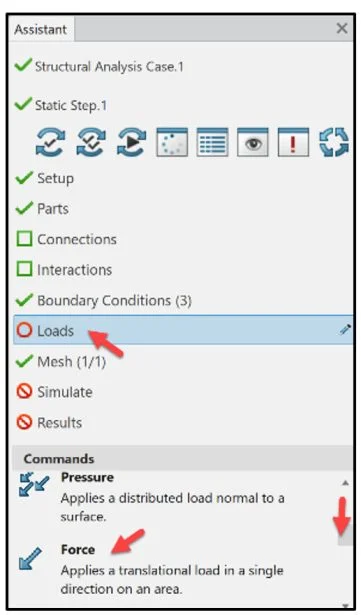
Click Loads from the Assistant dialog box. Click Force from the Commands box. Note: A force consists of three components: Transmission area, Direction and Magnitude.
Click the inside face of the model as illustrated.
Enter 400N in the Force X box.
Click OK.
Run Simulation
Run the Simulation study. Use the Physics Results Explorer App to manage results data from Simulations performed within the 3DEXPERIENCE platform or from other applications such as Abaqus.
Click Simulate from the Assistant dialog box.
Click Simulate from the Commands box.
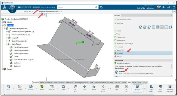
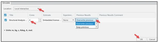
The Simulate dialog box is displayed.
It is recommended to run the Simulation using Local interactive. Local interactive is set by default using an embedded license. The Simulation is executed on your computer and the user interface is locked while the Simulation is in process.
With an Educational license, up to 4 physical cores are supported. Overwrite previous is selected by default. Note: Editing Units is only necessary if you plan to export an input file from Abaqus/CAE.
Click OK from the Simulate dialog box.
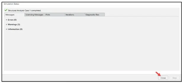
The Simulation Status dialog box is displayed.
Click Close.
Close the Assistant dialog box
Results Contour Plots
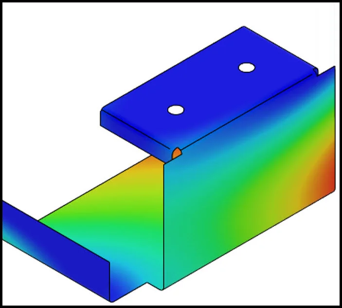
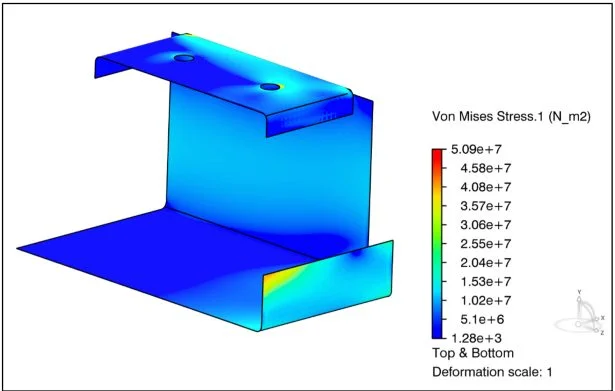
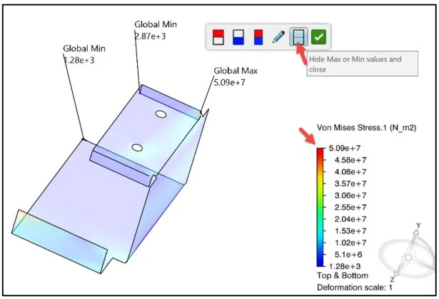
View the results. The Von Mises Stress contour plot is displayed by default.
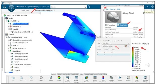
In this example, use the results plots for the Von Mises stress, Displacement, and Factor of Safety (FOS). Verify that the Von Mises stresses do not exceed the material’s yield strength. For most metals, the yield strength is defined as the stress point at 0.2% strain offset. For Alloy Steel this is (6.204 × 10⁸N/m2).The maximum Von Mises stress (5.09 × 10⁷N/m2) is below the material yield strength of (6.204 × 10⁸N/m2).Basics of Stress Limits for 3DEXPERIENCE – YouTube
Rotate the part to view the highest stress areas.
Click a point on the model as illustrated. The mouse cursor automatically acts as a probe.
View the Von Mises Stress at that point. A Pop-up menu is displayed.
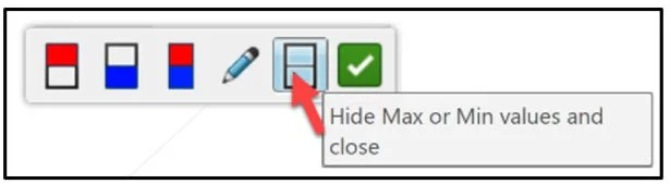
Click the Show Min/Max Values icon.
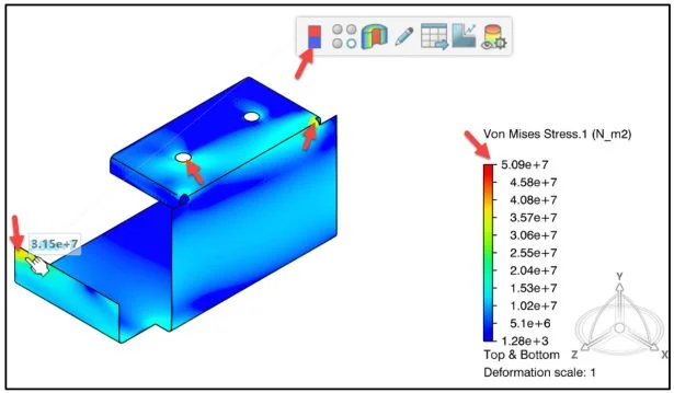
High stresses occur at the front edge, the first front hole and the top back edge of the model.
Click the Hide Max or Min values and close icon.
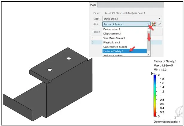
Create the Factor of Safety (FOS) contour plot. Range from 12.2 – 4.83 × 10⁵.
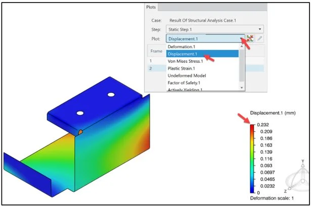
Create the Displacement contour plot. Range from 0 – .232 mm.
The mouse cursor automatically acts as a probe. Click a point on the model.
View the Displacement at that point. A Pop-up menu is displayed.
Click the Show Min/Max Values icon. View the results.
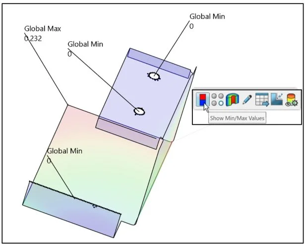
Hide the Max and Min values on the model.
Click the Hide Max or Min values and close icon.
Save the Simulation study.
Click the Share icon as illustrated.
Click Save. Model and Scenario data is always stored on the 3DEXPERIENCE server in your Collaborative space.
Results data may be stored on the server or in a local directory on your machine. Local data is masked, encrypted and only accessible by the owner of the data.
The default option is Server on the platform. Saving the Simulation Results data from a Simulation on the server allows other users in your Collaborative space to access that data and archive the data for future reference.
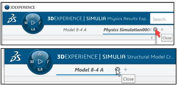
Close the Simulation study.
Click Close on the Physics Simulation0000XXXXX tab.
Click Close on the Model 8-4 A tab.
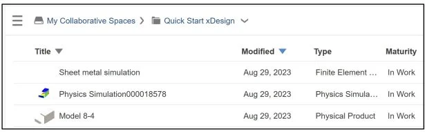
The below Simulation items are saved to my Collaborative space called Quick Start xDesign on the platform.
We are finished with this lesson.
Additional Lessons in 3DEXPERIENCE Simulation Series:
Analysis Lesson 1: SOLIDWORKS and 3DEXPERIENCE Simulation for Diving Board
Analysis Lesson 2: SOLIDWORKS and 3DEXPERIENCE Simulation Linear Structural Validation Part 1
Analysis Lesson 3: SOLIDWORKS and 3DEXPERIENCE Simulation Linear Structural Validation Part 2
Analysis Lesson 4: SOLIDWORKS and 3DEXPERIENCE Simulation Linear Structural Validation for Assembly
Additional Lessons in this series on 3DEXPERIENCE Works:
3DEXPERIENCE Works Lesson 1: Getting Started with SOLIDWORKS and the Platform
3DEXPERIENCE Works Lesson 2: SOLIDWORKS and Save and Revision
3DEXPERIENCE Works Lesson 3: SOLIDWORKS and Bookmarks, Share and Delete
3DEXPERIENCE Works Lesson 4: SOLIDWORKS and Lifecycle Maturity States
3DEXPERIENCE Works Lesson 5: SOLIDWORKS, Collaborative Space and Bookmarks
3DEXPERIENCE Works Lesson 6: SOLIDWORKS with Search Tools
3DEXPERIENCE Works Lesson 7: SOLIDWORKS with 3DPlay
3DEXPERIENCE Works Lesson 8: SOLIDWORKS with 3DDrive
3DEXPERIENCE Works Lesson 9: SOLIDWORKS and 3DSWYM
3DEXPERIENCEWorks Lesson 10: SOLIDWORKS and 3DEXPERIENCE Simulation
Additional Lessons in this series on SOLIDWORKS xDesign:
SOLIDWORKS xDesign Lesson #1: Getting Started
SOLIDWORKS xDesign Lesson #2: Mouse Control and Collaborative Space
SOLIDWORKS xDesign Lesson #3: Sketch Planes
SOLIDWORKS xDesign Lesson #4: Create A Dashboard
SOLIDWORKS xDesign Lesson #5: Views and Orientations
SOLIDWORKS xDesign Lesson #6: Importing Files and Using Bookmarks
SOLIDWORKS xDesign Lesson #7: Assemblies
SOLIDWORKS xDesign Lesson #8: 4Bar Linkage and Kinematics
SOLIDWORKS xDesign Lesson #9: External References and Copy with Mates
SOLIDWORKS xDesign Lesson #10: Sketching, Constraints and Dimensions
SOLIDWORKS xDesign Lesson #11: Sketch Based and Applied Features