
After teaching 1000’s of students and writing about SOLIDWORKS for over 25 years, David Planchard, emeritus WPI, is exploring xDesign. Through the SOLIDWORKS xDesign Lesson series, David helps educators understand the differences and similarities between xDesign and SOLIDWORKS through simple examples. He also introduces new apps in the engineering design process.
Features are the individual shapes that, when combined, make up the component.
Sketch based Features are features that originate with a sketch such as Extrude, Revolve, Sweep, and Loft. Applied Features require geometry from an existing feature such as Fillet, Draft, Shell, and Patterns.
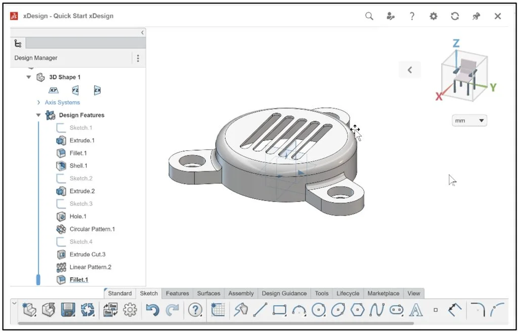
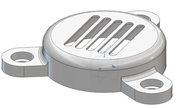
In this lesson, create a CAP component using the following feature types: Extrude, Extrude Cut, Shell, Circular Pattern, Linear Pattern, and Hole. xDesign Feature types are similar to SOLIDWORKS.
Apply the following Sketch entities: Circle, Line, Arc, Point, Slot, Mirror, Construction Line, Infinite Line, Convert, and Trim.
Manipulate the Design Manager: reorder a feature, edit the feature, utilize the rollback bar, deactivate and activate a feature and apply Design Assistance.
Through the years of teaching SOLIDWORKS, I tell my students three important sketching basics. 1. Select the correct sketch plane. 2. Keep the Base sketch simple. 3. Use constraints (geometric relations) before dimensions.
You should have a design strategy with your sketch profiles as you create the 3D features for the CAP component.
Use your unique link to the 3DEXPERIENCE platform.
Login to the 3DEXPERIENCE platform.
Start xDesign
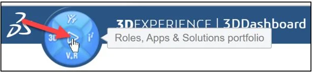
Click the center of the Compass as illustrated for Roles, Apps & Solutions portfolio.
Click 3D Designer (3D Creator) under My Roles. 3D Designer role is assigned to educators and students.
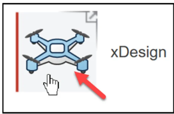
Click xDesign to launch the App or open an existing Dashboard with xDesign as a Widget.
xDesign has a single modeling environment. The term component is used because both parts and assemblies are treated the same. This is not true in SOLIDWORKS.
The default Name* of the component is Physical Product 1.
The default Location defines the Collaborative space (cloud storage) where your components are saved. This makes it easy to communicate and share designs with your students and team members, regardless of physical location.
The default Location maybe named: Common Space. Collaborative space location will differ depending on setup.
The 3DSpace App is used to create Collaborative space locations. The Quick Start xDesign Collaborative space and the 3DEXPERIENCE mouse control is used in the lesson.
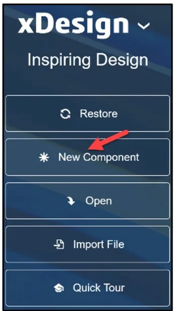
Create a new component
Click New Component.
Rename component to CAP.
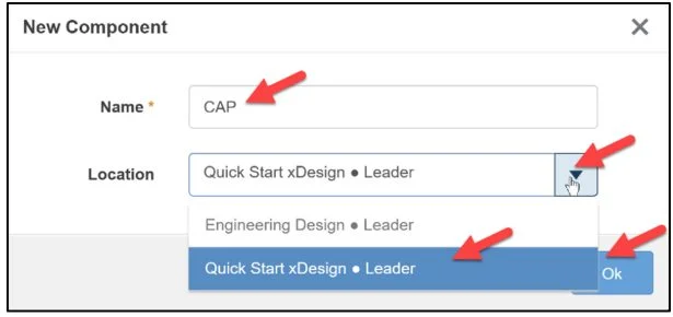
Click OK.
The xDesign App is displayed.
Trimetric Planes xy, yz, zx are located at the center of the Work Area.
The default axes are: +x, +y, +z.
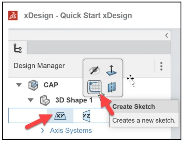
Create Sketch.1
Sketch.1 is normal to the xy plane (Top). Quick Start xDesign is the Collaborative space. When you create a new component, the three default planes (xy), (yz), (zx) are aligned with specific views. The plane you select for your first sketch determines the orientation of the part. Selecting the correct plane to start your model is very important.
Click the xy plane in the Design Manager.
Click Create Sketch from the Context toolbar.
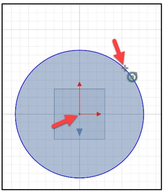
Create a circle. Locate the center of the circle at the Origin.
Click Circle from the Sketch tab in the Action bar.
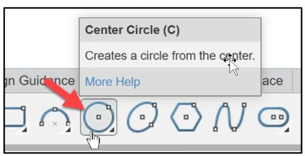
Click the Origin. This is the first point of the circle. It is very important that you always reference the sketch to the Origin. This helps to fully define the sketch.
Move the mouse icon out as illustrated. Click a position.
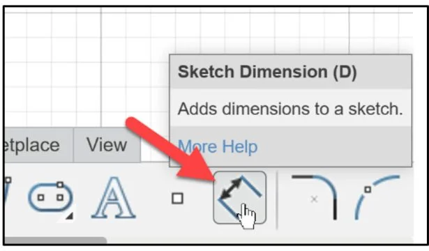
Dimension the circle. The default units are in Millimeters.
Click Sketch Dimension from the Sketch tab in the Action bar.
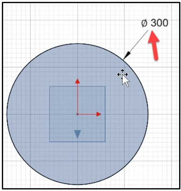
Enter the Diameter.
Enter 300mm.
Apply an Extrude Feature
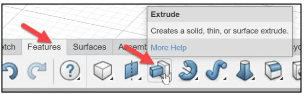
An Extrude is a Sketch based feature. The Extrude feature adds material to the component. An extrusion extends a profile along a path normal to the profile plane for a specified distance. The movement along that path becomes the solid 3D model.
Click Extrude from the Features tab in the Action bar. The feature icons are similar to SOLIDWORKS.
The Extrude Dialog box is displayed. In SOLIDWORKS this is called the Extrude PropertyManager.
Sketch.1 is displayed in the Profiles selection box.
Select Blind for Direction 1 from the drop-down menu. This is similar in SOLIDWORKS to select an End Condition.
Enter 80 for Distance.
Click OK (green checkmark) to complete the command.
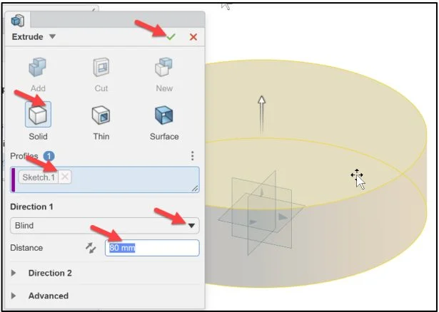
Extrude.1 is displayed. Sketch.1 is fully defined.
Fit the model to the Work Area. Display an Isometric view.
Press the f key to fit the model to the Work Area. Press the Ctrl+7 keys for an Isometric view. This is a similar in SOLIDWORKS.
Apply a Constant Fillet Feature to the top edge
Fillet Features create a rounded internal or external face on the component.
Click Fillet from the Features tab in the Action bar.
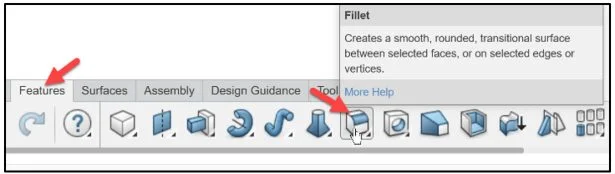
The Fillet Dialog box is displayed. In SOLIDWORKS this is called the Fillet PropertyManager.
Constant Fillet is selected by default.
Click the top edge of the component as illustrated. Edge.1 is displayed in the Entities box.
Enter 20mm for Radius.
Click OK (green checkmark) to complete the command.
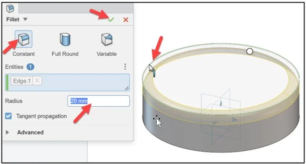
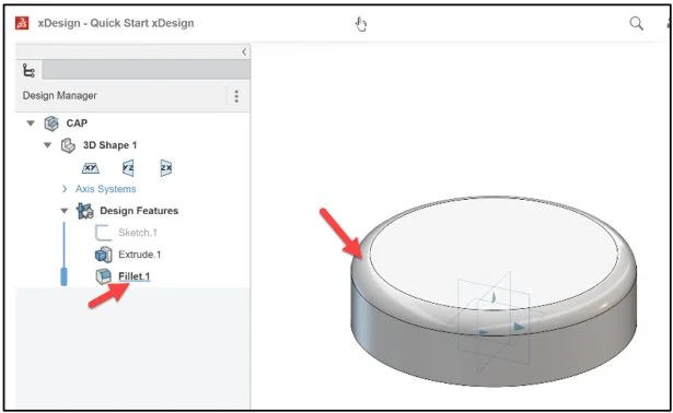
Fillet.1 is displayed in the Work Area.
The Shell Feature
Apply the Shell Feature with uniform thickness to the bottom of the component. The Shell feature hollows out a component.
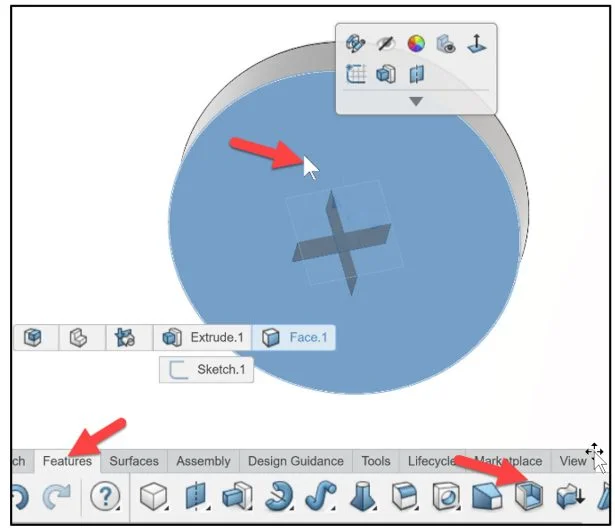
Rotate the CAP to view the bottom.
Click the bottom face.
Click the Shell Feature the Features tab in the Action bar.
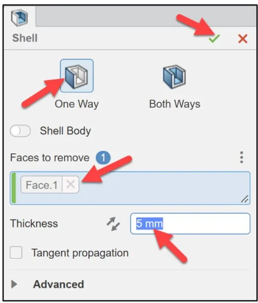
The Shell Feature Dialog box is displayed. In SOLIDWORKS this is called the Shell PropertyManager.
One Way is selected by default. Face.1 is displayed in the Entities box.
Enter 5mm for Thickness.
Click OK (green checkmark) to complete the command.
Shell.1 is created.
Create a tab
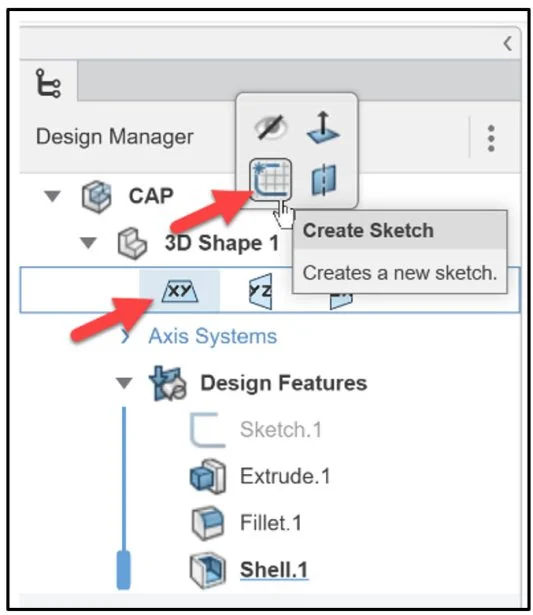
Start the sketch on the xy (Top) plane.
Click the xy (Top) plane.
Click Create Sketch.
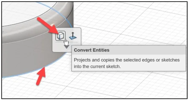
Rotate the component to view the outside bottom edge as illustrated.
Click the outside bottom edge.
Click Convert Entities from the General content box.
Return to a Top view.
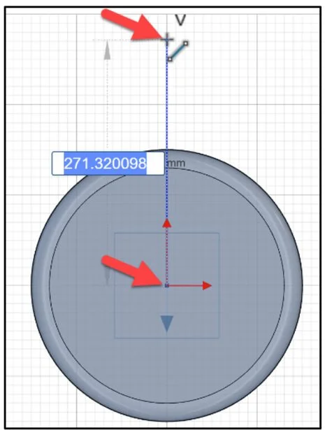
Create a vertical Construction line from the Origin upward approximately 270mm. Note: Construction geometry is used to assist in creating the sketch entities and geometry that are ultimately incorporated into the Component. In xDesign, you need to dimension the Construction line relative to the Origin. This is NOT the case in SOLIDWORKS.
Click Line from the Sketch tab Action bar.
Click the Origin.
Click a position above the Origin (approximately 270mm).
Press the Esc key.
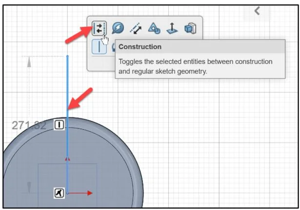
Click the vertical line.
Click Construction from the Content box.
Sketch a vertical line as illustrated approximately 70mm.
Sketch a 90 degree Tangent Arc between the vertical line and the construction line. Note: Add constraints if required.
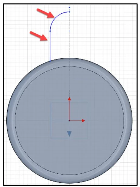
Press the Esc key.
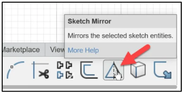
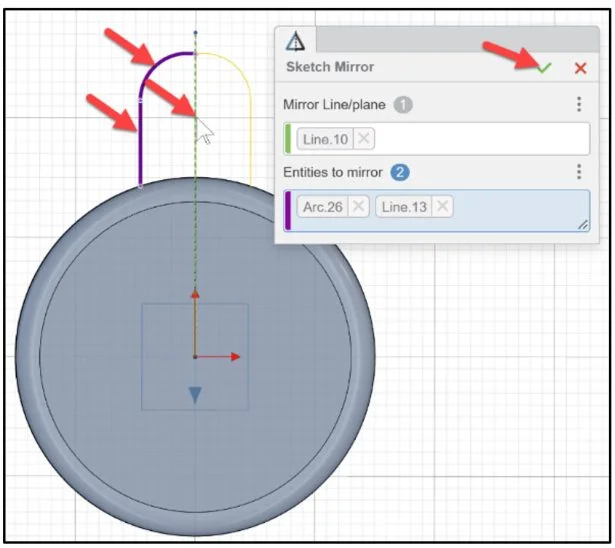
Mirror the line and arc sketch entities about the Construction line.
Click Sketch Mirror from the Action bar.
Click inside the Mirror line/plane box.
Click the Construction Centerline.
Click inside the Entities to mirror box.
Select the vertical line and the 90 degree Tangent Arc.
Click OK (green checkmark) to complete the command.
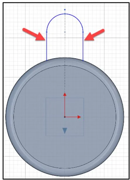
View the results.
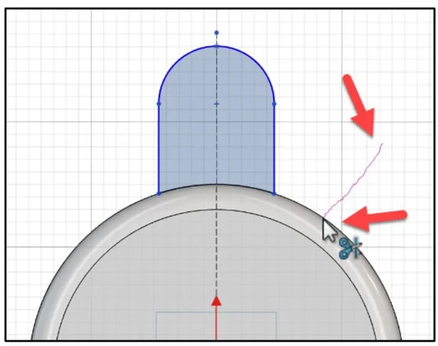
Trim the un-wanted sketch entity.
Click Trim from the Sketch tab Action bar.
Click and drag Trim as illustrated to remove the unwanted sketch entity.
Dimension the sketch.
Click Sketch Dimension from the Action bar.
Enter 250mm between the Origin and the top arc point.
Enter 100mm between the two vertical lines.
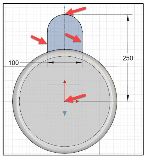
Sketch.2 is not fully defined. In xDesign, you need to dimension the Construction line to have fully defined Sketch.2.
Modify the Construction line to an Infinite line.
Click the Construction line.
Click Infinite line.
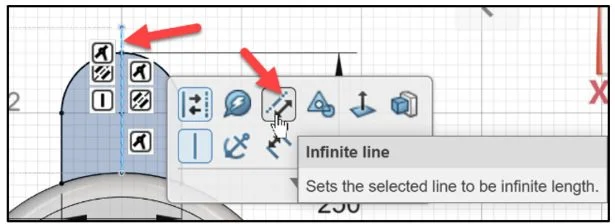
Sketch.2 is fully defined.
Create an Extrude feature.
Click Extrude from the Feature tab in the Action bar. The Extrude dialog box is displayed.
Solid is selected by default.
Select Blind for Direction 1.
Enter 30mm for Distance.
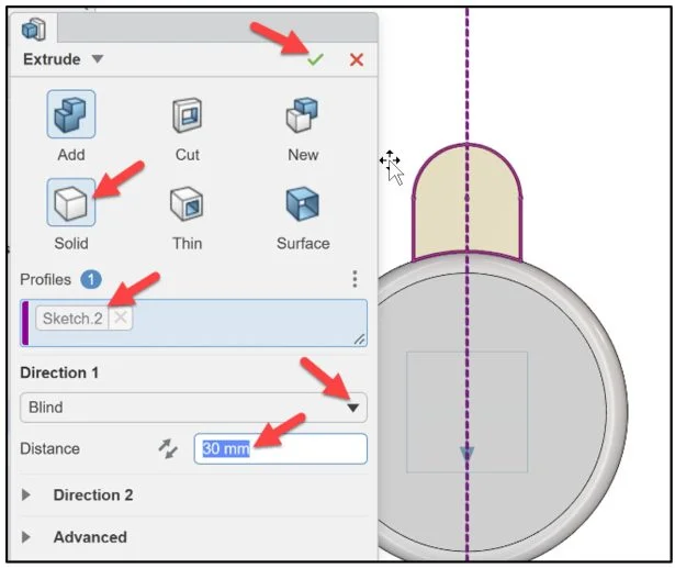
Click OK (green checkmark) to complete the command.
Extrude.2 is created.
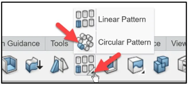
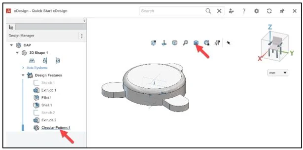
Create a Circular Pattern of the tab
Click Extrude.2 in the Design Manager.
Click Circular Pattern in the Feature tab Action bar.
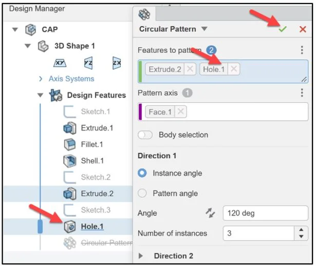
The Circular Pattern dialog box is displayed. Extrude.2 is displayed in the Features to pattern box.
Click the top face of the CAP component in the Work Area. Face.1 is displayed in the Pattern axis box.
Enter 120 for Angle.
Enter 3 for Number of instances.
Click OK (green checkmark) to complete the command.
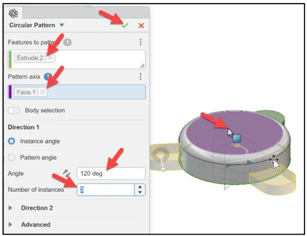
Circular Pattern.1 is created.
Display a Trimetric view of the CAP. View the Design Manager.
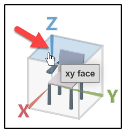
Display a Top view.
Click the xy face of the Triad. The Top view is displayed in the Work Area.
Create the Hole Feature
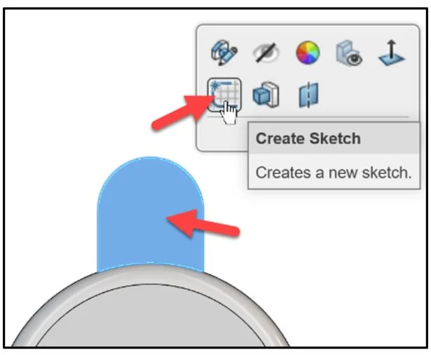
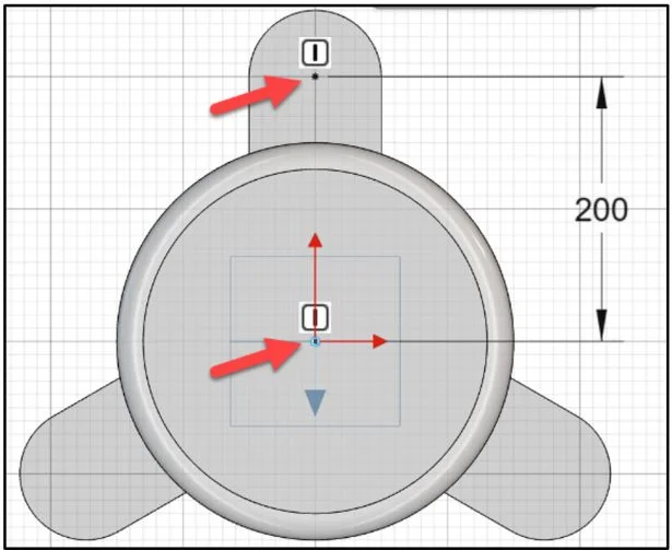
Insert a sketch point on the first tab for the Hole Feature.
Click the top face of the first tab.
Click Create Sketch from the Content box.
Click Point from the Action bar.
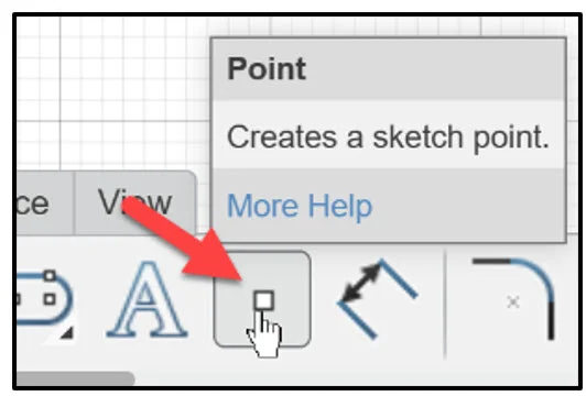
Click the center of the arc.
Create a fully define sketch.
Enter 200mm for distance between the point and the Origin.
If needed, insert a vertical constraint between the point and the Origin.
Create a Hole Feature. Click Hole from the Feature tab in the Action bar.
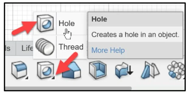
The Hole dialog box is displayed.
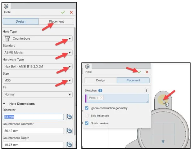
Select Counterbore for Hole Type.
Select ASME Metric for Standard.
Select Hex Bolt – ANSI B18.2.3.5M for Hardware Type.
Select M30 for Size.
Accept the other defaults.
Click Placement to place the hole.
Click the point. Point.1 is displayed in the Sketches box.
Click OK (green checkmark) to complete the command.
Hole.1 is created.
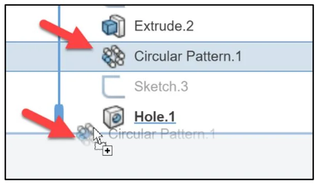
Reorder Features
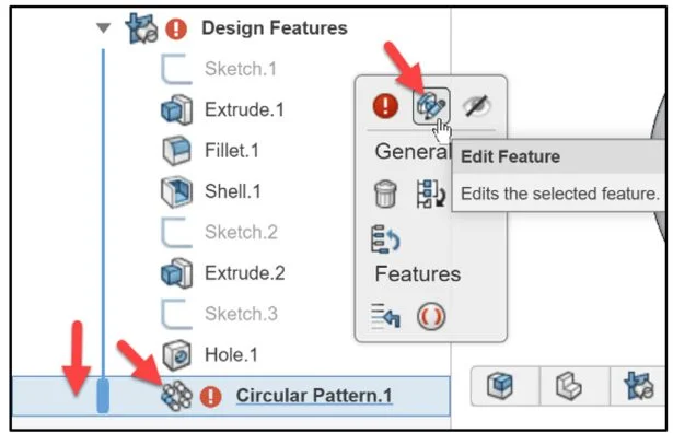
Reorder the Circular Pattern feature after the Hole feature in the Design Manager. Edit the Circular the Pattern to include the Hole feature in the tab.
Click Circular Pattern.1
Drag Circular Pattern.1 below Hole.1
Slide the Rollback bar downward.
Right-click Circular Pattern.1.
Click Edit Feature from the Content box.
The Circular Pattern dialog box is displayed. Add Hole.1 to the Features to pattern box.
Click Hole.1 in the Design Manager.
Click OK (green checkmark) to complete the command.
View the updated component in the Work Area.
Create a Extrude Feature with a Slot Sketch
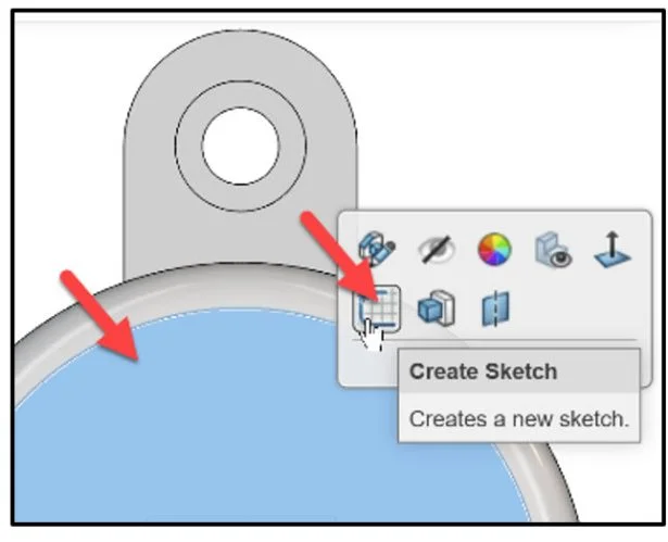
Create the first slot shaped feature on the top face of the CAP.
Click the top face of the CAP
Click Create Sketch.
Create an Infinite horizontal line through the Origin. This line will be used for the Linear Pattern reference.
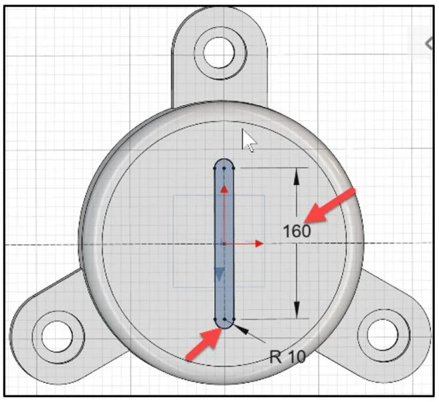
Create a Midpoint Centerline Slot.
Click Midpoint Centerline Slot from the Features tab in the Action bar.
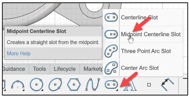
Click the Origin. Click a vertical position above the Origin approximately 160mm.
Click a horizontal position directly to the right of the center of the arc approximately 20mm.
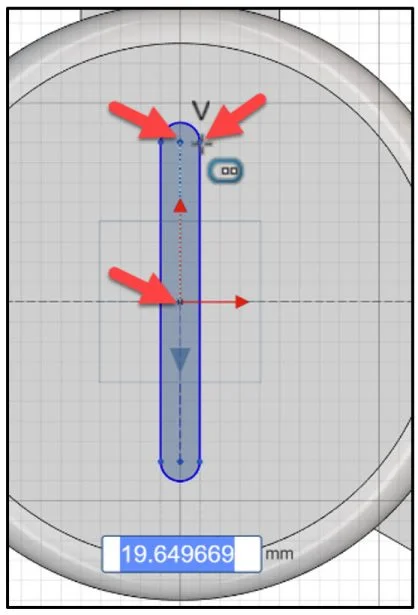
Dimension the Slot sketch as illustrated. Sketch.4 is fully defined.
Create the Extruded Cut feature for Sketch.4
Click Extrude Cut from the Features tab in the Action bar.
Sketch.4 is displayed in the Profiles box.
Select Through one way for Direction 1. Click OK (green checkmark) to complete the command.
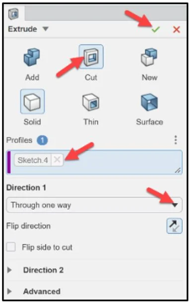
Extrude Cut.3 is created.
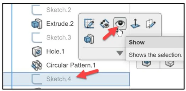
Show Sketch.4 from the Design Manager. View the infinite line.
Click Sketch.4 in the Design Manager. Click Show from the Content box.
Create the Linear Pattern of Extrude Cut.3
Click Linear Pattern from the Features tab Action bar.
Extrude Cut.3. is displayed in the Features to pattern box.
Click the infinite line in the Work Area. Line.1 is displayed in the Direction box.
Select Instance spacing. Enter 30mm for Spacing. Enter 3 for Number of instances.
Select Geometry pattern under the Advanced option. Select Symmetry.
Click OK (green checkmark) to complete the command.
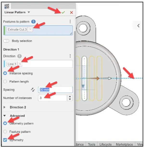
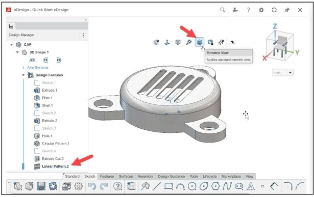
Linear Pattern.2 is created
Display a Trimetric view.
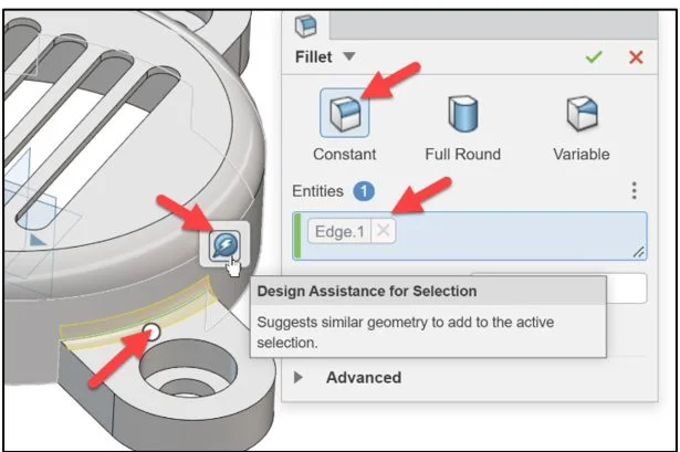
Create a Fillet with Design Assistance
Add a Constant Fillet Feature to the top of the three tabs. Use the Design Assistance. A Fillet/Round creates a rounded internal or external face on the component.
Zoom-in on a tab. View the top edge.
Click Fillet from the Feature tab in the Action bar.
Enter 10mm for Radius. Constant is selected by default.
Click the top edge of the tab as illustrated.
Click OK (green checkmark) to complete the command.
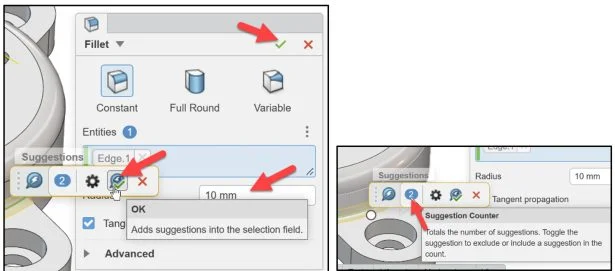
Click Design Assistance.
The Design Assistance (AI) displays a preview of two additional fillets on the other tabs.
Click OK from the Design Assistance.
Click OK (green checkmark) to complete the command.
Deactivate Fillet.1. Note: In SOLIDWORKS it’s called Suppress.
Click Fillet.1 in the Design Manager. Click Deactivate Feature.
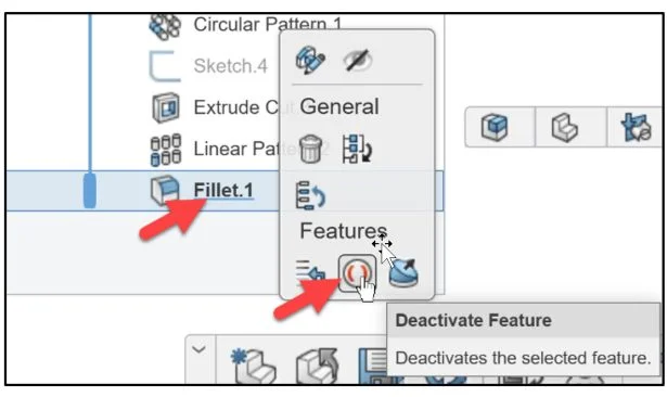
Fillet.1 is deactivated. View the Work Area and the Design Manager.
Active Fillet.1
Click Fillet.1 in the Design Manager. Click Activate. Note: In SOLIDWORKS it’s called Unsuppress.
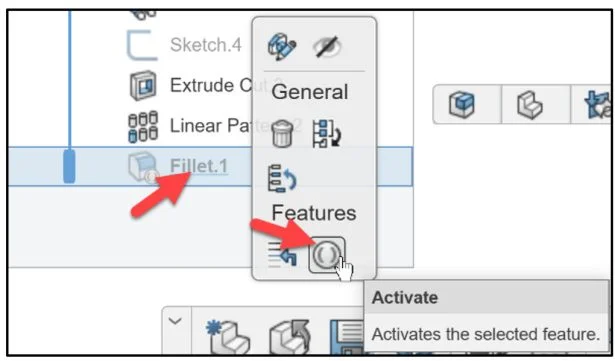
Fillet.1 is activated. The CAP component is finished.

Save and Close the CAP component.
Academic Community: After you create a 3DEXPERIENCE ID, Educators, can get more information on xDesign and SOLIDWORKS. Request to join the 3DEXPERIENCE Academic Community for free at go.3ds.com/academiccommunity.
Student Community: Students, join the student community for free at go.3ds.com/studentcommunity. Check out great posts on Mechanism Mondays, FEA Fridays, Solid Saturdays (animations), Formula Student and Formula SAE exercises.
Stay tuned for David’s new series of 3DEXPERIENCE Works Lessons featuring SOLIDWORKS Desktop and the 3DEXPERIENCE Platform.
To review the previous lessons, go to:
SOLIDWORKS xDesign Lesson #1: Getting Started
SOLIDWORKS xDesign Lesson #2: Mouse Control and Collaborative Space
SOLIDWORKS xDesign Lesson #3: Sketch Planes
SOLIDWORKS xDesign Lesson #4: Create A Dashboard
SOLIDWORKS xDesign Lesson #5: Views and Orientations
SOLIDWORKS xDesign Lesson #6: Importing Files and Using Bookmarks
SOLIDWORKS xDesign Lesson #7: Assemblies
SOLIDWORKS xDesign Lesson #8: 4Bar Linkage and Kinematics
SOLIDWORKS xDesign Lesson #9: External References and Copy with Mates
SOLIDWORKS xDesign Lesson #10: Sketching, Constraints and Dimensions