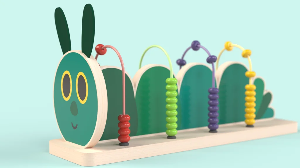
This is a fairly simple SOLIDWORKS tutorial, which encompasses several different features to create the Caterpillar shaped abacus. I enjoy creating tutorials like this, as beginners can follow along and see how a handful of features are used to design and model something entirely within SOLIDWORKS. Th decals that bring my design to life are available to download here.
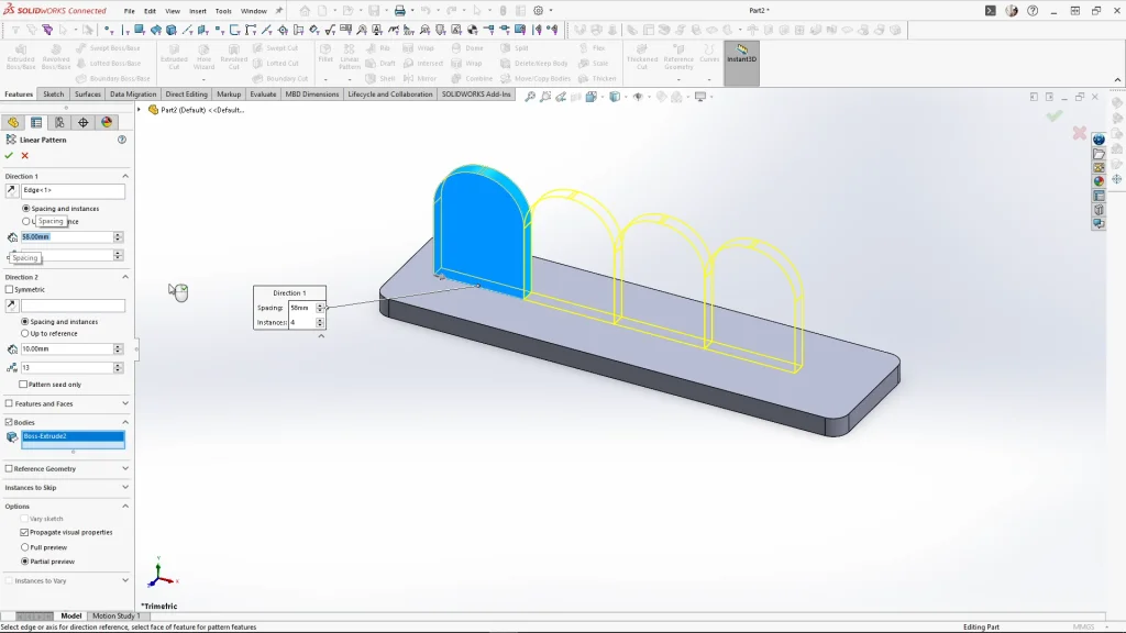
The main components of the caterpillar are simple sketches that are extruded. Sketching the caterpillar’s body, I simplified the design by only sketching a section of the caterpillar body first. The sketch was then fully defined. Using the Linear pattern feature, I chose the pattern direction, and selected the ‘Bodies’ box, to pattern the caterpillar body. I input 4 instances spaced apart by 58mm.
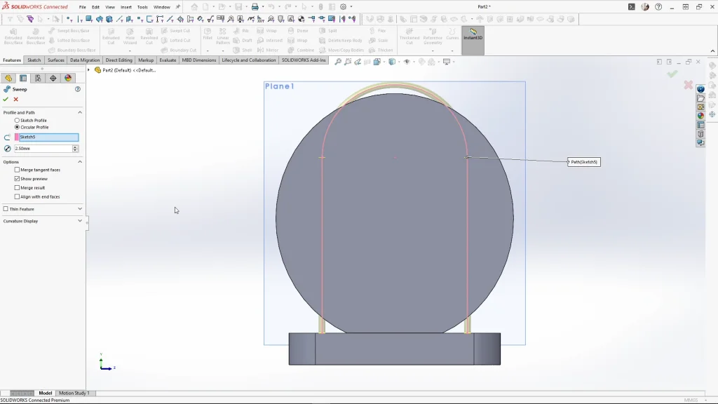
To create the wire tracks for the beads, I added a new plane midpoint to the caterpillar body segment. Sketching onto the new plane, I sketched an arch and fully defined the sketch. I then used the swept boss feature with a circular profile at 2.5mm, ensuring merge result is unchecked. I used the linear feature again to pattern the sweep bodies, I patterned the body by 4 instances by 58mm, and applied it.
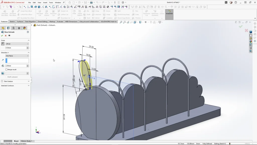
For the caterpillar antenna’s, I started a sketch on the caterpillar face. Using the extrude feature, I used the ‘from’ feature and changed the drop down to offset. Here I can offset the extrusion by 4.5mm midplane with a 2mm thickness, this extrudes the sketch in the middle of the caterpillar’s face extrusion.
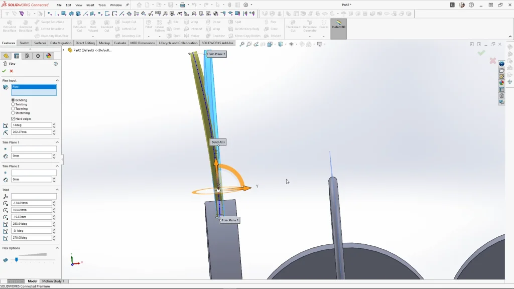
The antenna would be manufactured with felt fabric, keeping the body separate meant that I could flex the antenna body. Using the flex feature, I rotated the trim planes around to bend the antenna vertically by 22 degrees. Then repeated the feature again, only this time, I moved the bend axis line towards the bottom of the antenna, so I could bend the part by 14 degrees to look like the below image. I then mirrored over the antenna, selecting the front plane for my mirror plane.
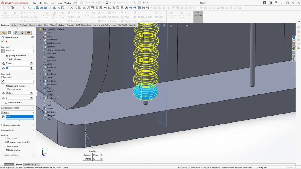
Moving onto the abacus beads, I sketched the beads top profile, extruded it by 6.5mm, offset from the base extrusions face. I then used the chamfer feature, and I chamfered the top and bottom outer edges of the bead. The edges were then softened using a fillet by 2mm. Patterning the bead, I used the linear pattern feature, changed the spacing to 6.5mm and the instances to 10. Instead of patterning the 10 beads along for the other 3 bead tracks, I used move/copy bodies, this choice is entirely for the ease of applying appearances later on. When I use linear pattern the bead solid bodies don’t group in order, whereas when I use move/copy bodies they stay grouped, making selections much easier.
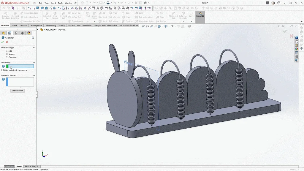
Using the move/copy bodies feature again, I created a copy of the antennas, but keeping them in the same position I used the combine feature. Changing the operation type to subtract, I selected the caterpillar face body for the main body, and a set of antennas for the bodies to subtract. This leaves a slot within the caterpillar head for the antennas to sit into.
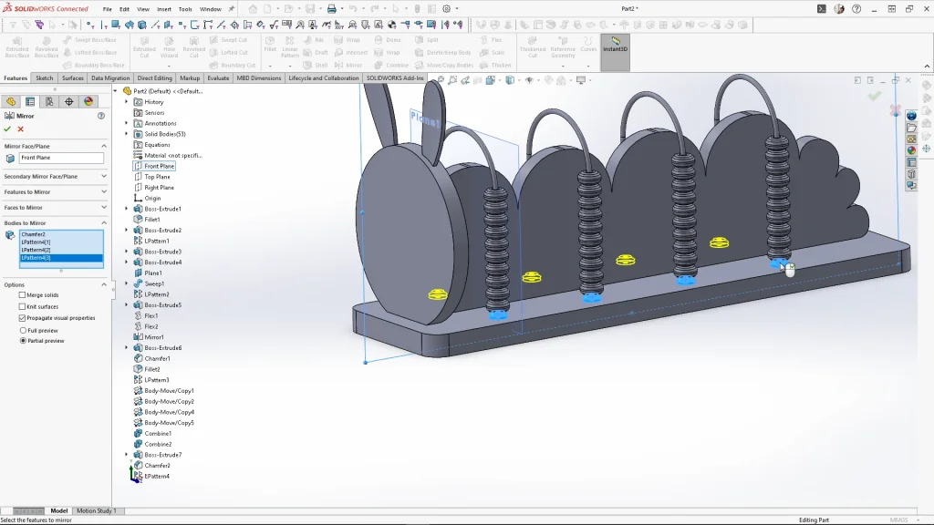
Selecting the combine feature again, I changed the operation type back to add, and selecting all the caterpillar segments I combined the bodies into one. Finally, I needed to model rubber stoppers for the bead tracks, these soften the drop of the wooden beads. Sketching, extruding and adding a chamfer to the rubber stoppers, I used the liner pattern the body. The distance between instances is 58mm, with 4 instances. Once applied, I used the mirror feature to mirror over the 4 rubber stopper bodies.
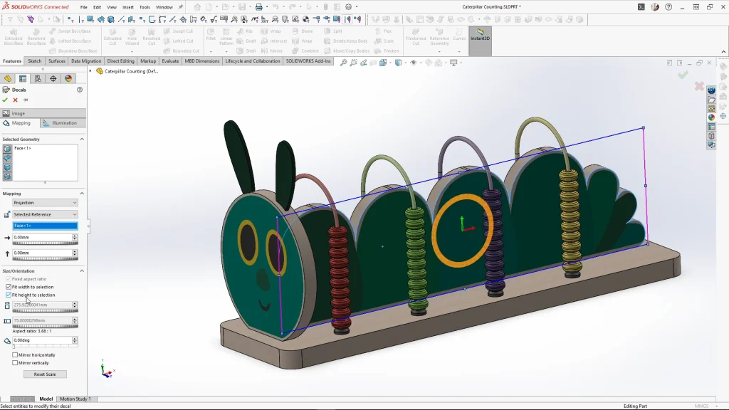
With the model is complete, I applied all of my appearances, and my custom decals to the model. My decals are PNG image files, so the background colour can be removed and reveal the appearance applied underneath. With the caterpillar abacus complete and saved. I created a motion study and animated the abacus, which was rendered in SOLIDWORKS Visualize, you can view this at the end of the tutorial.