
SOLIDWORKS users may be familiar with CAD-embedded simulation through exposure to tools such as SOLIDWORKS Simulation and SOLIDWORKS Flow Simulation for solving engineering problems with Finite Element Analysis (FEA) and Computational Fluid Dynamics (CFD). These tools can serve as both an excellent introduction to Computer Aided Engineering (CAE) in general and, in the hands of a skilled user, provide a way to get design-time predictions with a fair degree of accuracy.
If capabilities beyond these entry-level tools are needed, then Dassault Systèmes SIMULIA brand is the next step up in capability. The SIMULIA brand is best known for Abaqus/CAE, a desktop product featuring a powerful FEA solver that is widely used for its capabilities solving highly nonlinear problems. Nowadays, SIMULIA tools are also offered on the 3DEXPERIENCE platform with access to HPC resources for solving large simulations on the cloud and variety of solvers across many disciplines.
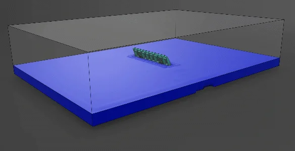
Figure 1. River dam solved in SIMULIA Fluid Dynamics Engineer.
This article will focus on the CFD capabilities in 3DEXPERIENCE SIMULIA Fluid Dynamics Engineer, and explores use cases for both SOLIDWORKS and non-SOLIDWORKS users to consider.
What is SIMULIA Fluid Dynamics Engineer?
SIMULIA Fluid Dynamics Engineer is a 3DEXPERIENCE role which grants several applications that together make up a powerful and general-purpose CFD software package. You may sometimes hear it referred to by its product code or “trigram” which is FMK.
The most noteworthy apps it includes are identified below:
- Fluid Model Creation
- Fluid Scenario Creation
- Physics Results Explorer
- Simulation Manager
In a conventional workflow, CAD geometry is brought into “Fluid Model Creation” for geometry abstraction and mesh generation. Then “Fluid Scenario Creation” is where the rest of the study pre-processing occurs: assigning boundary conditions, setting up output requests to monitor key results and adjusting solver options. Finally, results are interpreted in the “Physics Results Explorer” for post-processing.
In practice, all of this is achieved in a single cohesive user interface within 3DEXPERIENCE, with the loaded application automatically switching depending on the context of the command the user activates — so generally, you don’t have to worry about which application to use!
Example Setup Process
Let’s go over a quick run-down of the setup process.
The geometry can be brought over in several ways. 3DEXPERIENCE offers built-in connectors for SOLIDWORKS to provide an associative link to the CAD model, and connectors are also available for other CAD software as well, such as Creo and Inventor. That being said, you can always fall back to dragging over a .STEP file or another neutral CAD format if needed.
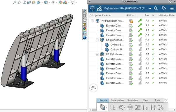
Figure 2. CAD Model import to 3DEXPERIENCE.
Once the model is uploaded to the 3DEXPERIENCE platform, the user can begin the setup process in the Fluid Scenario Creation app.
Similar to the SOLIDWORKS desktop simulation products, an assistant is available to guide the user through major setup considerations step-by-step, including defining the relevant physics and materials, setting up boundary conditions, and so on.
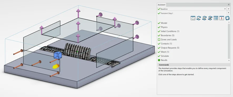
Figure 3. Fluid Scenario Creation.
Clicking on the “Model” or “Mesh” tabs from the Assistant will seamlessly switch the user over to tackle Mesh creation. The software typically defaults to a hex-dominant mesh with support for boundary layer elements, but other options such as tetrahedral and swept mesh are available.
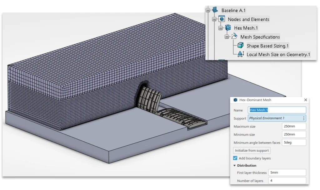
Figure 4. Fluid Model Creation.
Once everything in the assistant is green, the simulation should be ready to run. Once solved, the software will automatically switch over to Physics Result Explorer for post-processing. Clicking the “Results” tab in the assistant will accomplish the same thing.
System Requirements
The three apps discussed so far are cloud-connected, but do require local desktop installation. Complex tasks like mesh generation, solving and post-processing can be offloaded to cloud HPC resources, but it’s still a good idea to utilize a modern Microsoft Windows-based engineering workstation to ensure the required local setup goes smoothly.
The Simulation Manager app can be accessed through a web browser and allows some useful administrative functionality: monitoring any jobs that are submitted to track their progress while they are being solved, as well as identifying results files that are consuming large amounts of storage space. It also allows the user to delete either just the results, or the entire simulation.
Solver License Model
The base Fluid Dynamics Engineer role includes an “embedded license” which allows solving on up to 16 CPU cores, either on the cloud or locally, with no additional charges. The 16-core cloud instance is quite capable and was used to solve all the examples you’ll see throughout this article.
In any situation where the user may need > 16 CPU cores or more RAM than the base instance provides, they can utilize either tokens or credits to increase their licensed compute capacity.
Credits are a consumable resource sold in packs, and tokens are a “floating” style resource that are shared across an organization. For bursty workloads, credits almost always make sense. If there’s a significant baseline requirement for high compute, then tokens become more cost-effective.
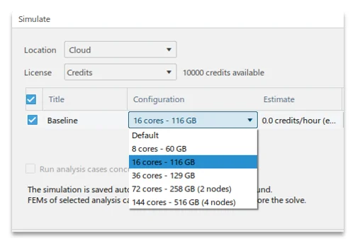
Figure 5. CPU Core Selection for Cloud Solve.
Either way, when selecting a larger instance type or specifying multiple simulations to solve in parallel, the software will provide either the required number of tokens or the estimated credit burn rate. In all cases, meshing and results post-processing is “free” and does not consume credits or require tokens.
So now that we’ve got some of the logistics out of the way, what are some reasons to use a tool like 3DEXPERIENCE SIMULIA Fluid Dynamics Engineer?
Use Cases for SIMULIA Fluid Dynamics Engineer
In the remainder of the article, we will identify use-cases for 3DEXPERIENCE SIMULIA Fluid Dynamics Engineer, with a specific focus on applications that either wouldn’t be possible or may be impractical in a more entry-level CFD software like SOLIDWORKS Flow Simulation.
Open Channel or “Free Surface” Problems
Open channel flows or “free surface” problems feature a liquid/gas interface, which is very common in water and waste management applications such as the flow of water through an open aqueduct or a partially filled pipe, or in marine applications such as boat hull resistance prediction. Most commonly in CFD, these tasks are accomplished using a numerical method such as the “Volume of Fluids” approach.
SIMULIA expands on the capabilities of SOLIDWORKS Flow Simulation for “Free Surface” problems in a few key ways:
- Greater performance
- Support for surface tension & capillary action
- Support for special boundary conditions
Firstly, the combination of a newer generation CFD solver and the HPC cloud resources means that, in my experience, free surface problems of moderate or high complexity will often solve much faster in SIMULIA Fluid Dynamics engineer than in SOLIDWORKS Flow Simulation. The animation at the start of this article depicting the river dam took only about 30 minutes of solve time on the default cloud instance.
Secondly, a major limitation in SOLIDWORKS Flow Simulation is that surface tension cannot be represented. In SIMULIA both surface tension and capillary action can be represented, as demonstrated in the simple proof-of-concept example below where a “straw” is inserted into a chamber of liquid with no other special treatments, and the liquid rises up the straw due to capillary action.
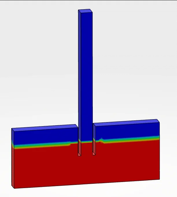
Figure 6. Simple example of capillary action in action.
Thirdly, the software provides a number of special boundary conditions that are useful for open channel problems. This includes a “floating elevation” inlet which avoids the chicken-and-egg problem of trying to predict the hydraulic height or inlet waterline for a system, and built-in support for wave generation for marine applications.
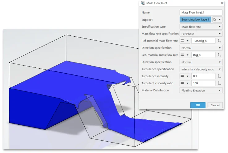
Figure 7. Dam spillway with “Floating Elevation” inlet.
Additionally, if a user requires custom functionality, User Defined Subroutines can be written in JavaScript to govern the behavior of boundary conditions.
Multispecies mixing with Absorption or Production
Multispecies flows, in basic terms, are those that represent mixing problems where two or more fluids of the same phase may be introduced and tracked through the overall flow.
Tools like SOLIDWORKS Flow Simulation are perfectly capable of simulating these behaviors in many scenarios, but one special case is when a specific species must be absorbed or produced through interactions with the model walls or other geometry. Here, the ability to specify absorption or production rates across specific selections becomes invaluable in Fluid Dynamics Engineer.
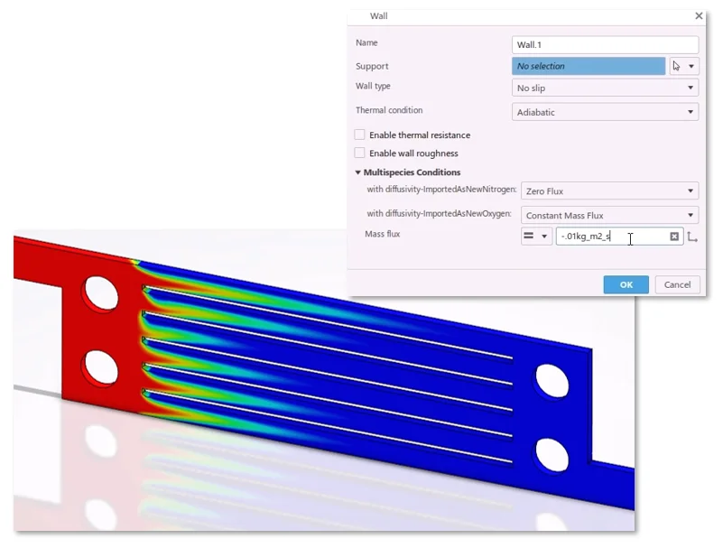
Figure 8. Absorption of gas species through walls.
The example above features a crude proof-of-concept model of a fuel cell with an absorption of one species representing a catalyzing reaction that would occur on the cell walls.
Problem Size
Some problems are simply too big to solve in any reasonable span of time on common PC hardware. For these cases, the access to higher-powered instance types (up to 144 cores at the time of this writing) is valuable.
Common cases that come to mind include analysis of large assemblies and systems, rotating machinery, or long-timescale thermal or mixing problems.
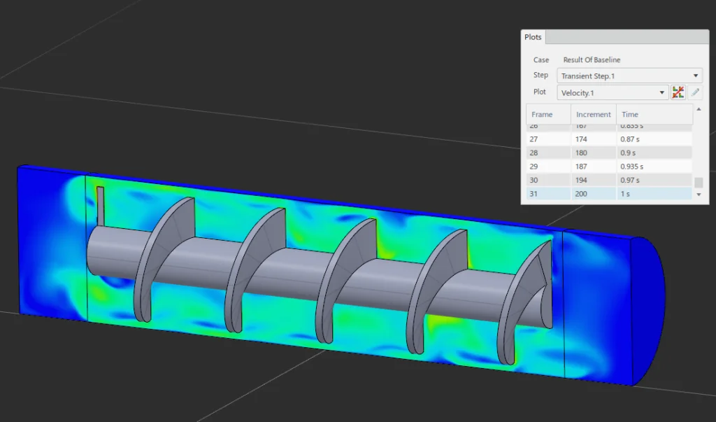
Figure 9. Rotating machinery example.
SIMULIA Fluid Dynamics Engineer has been shown to handle solutions for problems of greater than 100 million cells when using the top 144 core instance type. For long timescale transient problems, scaling the core count also provides a potential method to reduce solution time to manageable levels.
High Accuracy Drag Predictions
When predicting drag on bodies using Computational Fluid Dynamics, there are two main components of concern: “form” drag and “skin” drag.
Accurately capturing form drag is relatively straightforward and generally requires adequately resolving the overall shape of the geometry and wake region, as well as using an appropriate turbulence model.
Resolving skin drag to a high level of accuracy is more difficult, and happens to be especially important for increasing efficiency of aero and hydrodynamic applications such as aircraft, ships and rotating machinery such as pumps and impellers.
There are a couple key advantages offered by the SIMULIA tools here. “Body fitted” or conformal meshing allows capturing the precise shape of the CAD geometry efficiently with a minimal number of cells. Specialized boundary layer elements allow the user to either utilize wall functions or directly resolve the viscous sub-layer crucial to skin drag. This switchover occurs automatically depending on first cell height and the associated “y+” value.
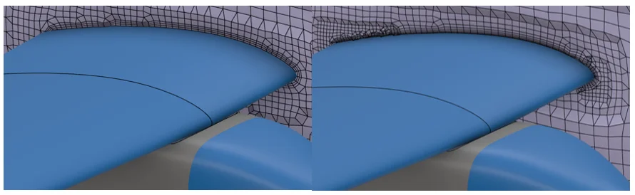
Figure 10. Body Fitted Mesh in SIMULIA Fluid Dynamics Engineer.
In SOLIDWORKS Flow Simulation, which uses a Cartesian grid system with cut-cells for the mesh, a couple problems can arise. Firstly, while this type of meshing system is great for blocky parts like those common in electronics cooling applications, when it comes to organically shaped parts a significant amount of mesh refinement may be required to even adequately resolve the geometry.
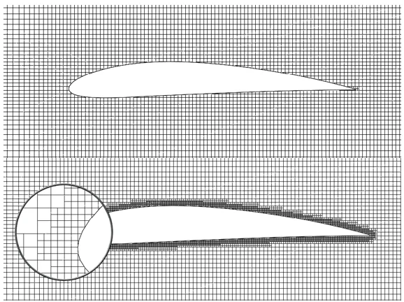
Figure 11. Cartesian “Cut Cell” Mesh in SOLIDWORKS Flow Simulation.
As you can see from the magnified view above, even with localized mesh controls placed there is still some geometric discretization error on the leading edge of the airfoil. Furthermore, since there is no dedicated boundary layer element definition there is not a practical means to fully resolve the viscous sub-layer if desired. In theory, the software would switch over to resolving the sub-layer if enough mesh refinement was present, but in practice it is just not feasible for real 3D problems with the nature of the meshing technology.
Another major advantage of SIMULIA Fluid Dynamics Engineer for high accuracy problems is the presence of additional turbulence models. While SOLIDWORKS Flow Simulation only offers a k-epsilon model, SIMULIA adds the popular general purpose SST k-omega model, as well as the Spalart-Allmaras model which is favored for many aerospace applications.
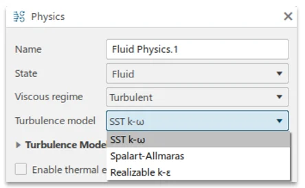
Figure 12. Available turbulence models.
Depending on the nature of the simulation, flow regime and industry standards, the user can select the most appropriate turbulence model for their application and gain back some of the accuracy that may be lost from using an inappropriate model.
Multiphysics Workflows
Another interesting workflow available in 3DEXPERIENCE SIMULIA is Multiphysics. It was previously mentioned that there are a variety of solvers available across different domains, and that the interface is relatively standardized between different tools.
This provides some great options as results from one study or type of study may be transferred to another to tackle Multiphysics simulations. And compared to having to learn multiple unique software packages, the user experience of jumping in and out of a CFD study into a FEA is quite straightforward.
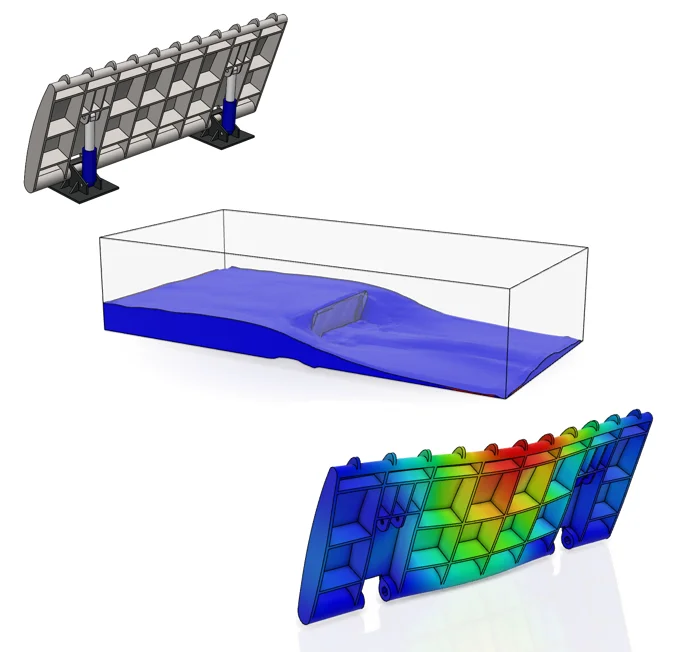
Figure 13. CAD Model, Fluid Simulation and Structural Simulation.
In the example above, the end goal is to analyze the river dam’s stresses and deflection subject to the loading it would experience from a flood condition. The CAD model was first imported to SIMULIA Fluid Dynamics Engineer and analyzed as a “Volume of Fluids” or Free Surface simulation.
The end goal for this endeavor was to map the calculated fluid pressures from the faces of the dam to an associated structural analysis in SIMULIA Structural Mechanics Engineer.
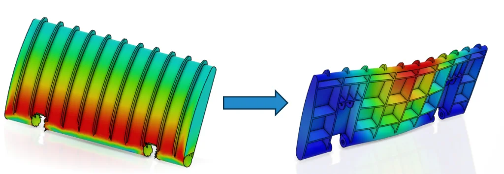
Figure 14. Desired pressure mapping.
To accomplish this, a “Port Region” was defined on the desired faces from the dam, allowing to link the associated field to a downstream simulation.
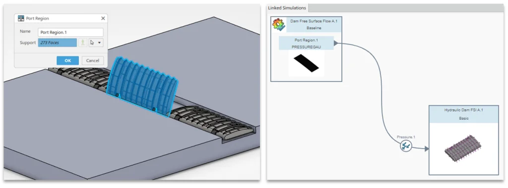
Figure 15. Port Region definition.
Once the Port Region is defined, the pressure field can be easily imported into a structural analysis as a loading. Both studies can be solved sequentially to perform a “one-way” fluid structure interaction or FSI analysis.
Note that it’s also possible to map other physical behaviors, such as temperature gradients from a thermal CFD analysis to a structural study for thermal stress prediction, or even data from other solvers such as electromagnetic analysis.
Summary & Conclusion
3DEXPERIENCE SIMULIA Fluid Dynamics Engineer provides a step up in CFD capabilities compared to what is available in entry-level tools such as SOLIDWORKS Flow Simulation. By leveraging the latest solver technology, access to scalable cloud HPC resources and specialized boundary conditions, it enables the study of problems that would otherwise be impractical—such as free surface flows with surface tension, multispecies mixing with absorption or production and high-fidelity drag predictions requiring body-fitted meshes and advanced turbulence models.
The workflow within 3DEXPERIENCE is straightforward from geometry import through meshing, solving and post-processing, while offering flexibility in the available compute resources through tokens or credits. This balance of usability and computational depth makes it well suited to handle larger assemblies, long-timescale simulations and Multiphysics workflows such as fluid–structure interaction.
That being said, it isn’t necessarily the obvious choice for all use cases. There’s still a strong argument to be made to consider a truly CAD-embedded CFD tool if all you need is quick design time checks and iteration where you may not care about the last few percent of accuracy. SOLIDWORKS Flow Simulation’s meshing technology also makes it incredibly well suited for specific tasks like electronics cooling, and while SIMULIA Fluid Dynamics Engineer can solve these studies too, it may require more setup time and geometry preparation.
For engineers who need to move beyond desktop-based CFD or take advantage of more advanced physics, however, SIMULIA Fluid Dynamics Engineer provides a viable option with accuracy, scalability and the solver options required for advanced analysis across a wide range of applications.