
Motion Analysis in SOLIDWORKS is a powerful tool that is often underutilized. It expands on SOLIDWORKS’ built-in assembly motion capabilities (such as real-time collision detection) to provide a full-fledged multibody dynamics simulation that can be used for a wide variety of engineering applications.
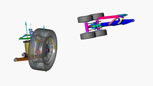
Figure 1. Example mechanisms analyzed with SOLIDWORKS Motion.
More precisely, Motion Analysis provides “rigid body dynamics” or “rigid body kinematics.” This defines one of the key aspects of SOLIDWORKS Motion: that all bodies involved in the simulation are treated as non-deformable.
This rigid body assumption tends to be appropriate for a wide breadth of physics and engineering problems. Common applications may range from prediction of forces and range of motion for mechanisms and linkages, to sizing motors, springs and dampers for dynamic systems, or predicting physics that require complex 3D contact interactions such as objects moving through hoppers or along conveyors.
We’ll cover many such cases in this article, with a focus on when the tool can and should be used and details on key setup considerations for different classes of problem.
Types of Motion Studies and Licensing
If you’ve ever created a “motion study” in SOLIDWORKS, you’ve probably seen that there are several tiers of functionality available.
- Animation: Keyframe-based animation, strictly for visuals that don’t involve complex physics.
- Basic Motion: Video game-style physics (powered by Nvidia PhysX) that can believably simulate complex 3D physics, but cannot be used for engineering data or decisions.
- Motion Analysis: Robust engineering-grade solver (powered by ADAMS) for dynamics and kinematics including prediction of forces
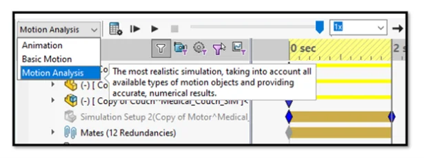
Figure 2. Choosing study type.
Of these options, Animation and Basic Motion are included in all versions of SOLIDWORKS. Motion Analysis, however, is only included in SOLIDWORKS Premium (and equivalent 3DEXPERIENCE SOLIDWORKS Premium), or SOLIDWORKS Simulation packages.
It’s also worth pointing out that it’s an add-in that must be enabled in SOLIDWORKS, so if you believe you should have access to it but don’t see it in your options, check to make sure the add-in is loaded.
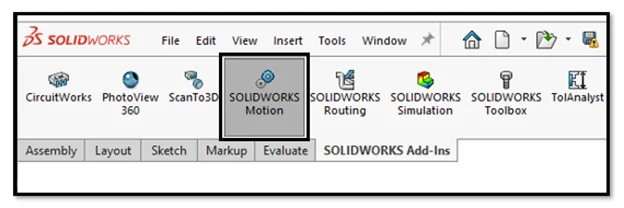
Figure 3. Ensure the Motion add-in is loaded.
Note that there is an additional caveat regarding a subset of Motion functionality called “event-based” motion that we’ll discuss later in the article.
Analyzing Mechanisms
Perhaps the most obvious applications for Motion Analysis are the design and analysis of mechanisms, such as the automotive suspension and the landing gear pictured at the beginning of the article.
We’ll start our journey by analyzing a very simple case – the equivalent of “Hello World” for any dynamics analysis, the four-bar linkage.
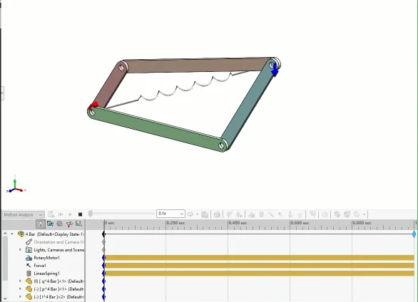
Figure 4. A simple four-bar linkage setup.
In this case, a virtual motor is defined to induce the rotation. An arbitrary force was applied to generate some resistance, and a virtual spring was defined between some points to make things more interesting.
You may also spy a “trace path” that has been placed on the point of force application. These paths can be converted into SOLIDWORKS sketches, which can be useful for defining keep-out zones or performing mechanism synthesis.
Sizing Motors & Actuators
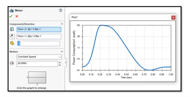
Figure 5. Motor definition and power consumption plot.
There are many options for defining motors and linear actuators. This example uses a simple constant speed motor, but they may be defined with complex behaviors including imported data or user expressions. Resulting forces, torque and power can be extracted to size motors or as a metric for further optimization.
Preparing Assemblies for Motion Analysis
Let’s discuss the best and worst thing about using SOLIDWORKS Motion for your assembly analysis: it uses your existing assembly mates.
On the surface, this seems great! However, in practice, it means some users run into difficulties trying to take their complex assemblies and toss them into Motion Analysis.
There are two main challenges here that need to be addressed:
- Components must be mated in a physically correct way.
- Redundancies must be addressed.
Firstly, for Motion Analysis there are entire mating techniques that I would generally consider to be a best practice — such as mating between reference points, coordinate systems, or other abstract reference geometry — that are usually unacceptable for accurate force extraction in motion studies.
The most tried and true way I’ve found to mate an assembly for Motion is to suppress any pins, axles or fasteners and simply follow the load path, and mate each component’s faces together where the associated fastener or connector would go. This may mean creating new configurations of your assembly, or in some cases building a second assembly from the ground up with a Motion analysis mating scheme in mind.
In the example of the simple four-bar linkage, the fasteners are omitted and the individual links are mated concentrically based on their holes. The bottom link is fixed and the remaining links have the necessary degrees of freedom in the assembly to allow the appropriate movement.
Figure 6. Bushing definitions.
Once the Motion Analysis is active, you’ll find additional settings under an “Analysis” tab for any of the mates. This allows defining more physically-based information like friction and stiffness to the mates. I recommend taking advantage of the “bushing” functionality to assign some defined stiffness to these virtual connections, which will help avoid any issues with redundancies when it comes time to extract forces.
Battling Redundancies
If you’re familiar with linear statics problems, you may remember the case of a “statically indeterminate” problem. Imagine a door hanging from two hinges and subject to nothing but its own weight from gravity. We know intuitively that each hinge should carry about half the weight, but this type of determination relies on elastic deformation somewhere in the system.
In a perfectly rigid assumption (like the default behavior in SOLIDWORKS Motion) it is indeterminate, and you may find all the weight carried by the top hinge or the bottom with seemingly no rhyme or reason. Applying bushings with stiffness, even a very high stiffness, will allow some deformation to occur, which should be enough for the system to self-equilibrate.
Optimization
Once an initial study is set up, it’s easy to perform further iteration or optimization by taking advantage of SOLIDWORKS Design Study capabilities, which work nicely with SOLIDWORKS Motion. Here I’m automatically varying the dimensions of a couple links in a table-based approach, and I can access the motion results for any individual scenario by simply selecting it, if I’d like to dive further into the results for that iteration.
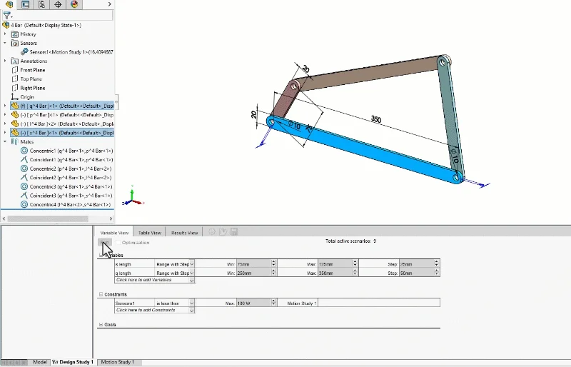
Figure 7. Design Study for mechanism optimization.
Determining Range of Motion & Trace Paths
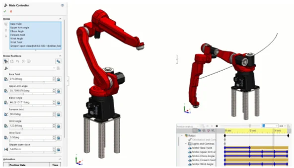
The “trace path” functionality in SOLIDWORKS Motion allows tracking the movement of any point in the model over the course of the study, which can be very useful for establishing range of motion. In this example of a 6-DOF robotic arm, the motion was prescribed using the “Mate Controller” functionality in SOLIDWORKS, which is a convenient way to control individual axes similar to how you might use jog handles on a robot’s pendant control.
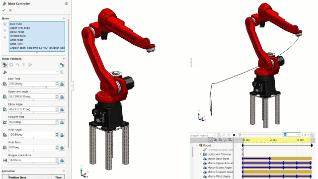
Figure 8. Robotics range of motion using the Mate Controller and Trace Path.
Once you’re happy with the behavior of the Mate Controller, you can create a motion study and use the wizard to import the path. This allows extraction of forces within the motion study, as well as generating trace paths.
Photo Rendering & Product Visualization
Motion Analysis is great for getting engineering data, but there’s some fun to be had too. Motion studies can be rendered in tools like SOLIDWORKS Visualize, something I did years ago for the example below. The camera movement was keyframed manually, but the physics of the dice are purely from SOLIDWORKS Motion, with solid contact and initial velocity defined to represent the dice roll.

Figure 9. Motion study rendered in SOLIDWORKS Visualize.
There are serious applications here for product visualization, particularly if there are any contact interactions involved.
The latest versions of SOLIDWORKS also support exporting 3D models (with Motion studies) to .GLTF or .GLB format which is a VR/AR/web-friendly model standard. You can read more about this in the SOLIDWORKS Help Files.
Predicting Complex Contact
For behaviors that aren’t captured by mates, SOLIDWORKS Motion supports contact interaction including fairly robust 3D contact interactions. Second to mates/redundancies, contact issues seem to be the most common place users run into trouble with SOLIDWORKS Motion.
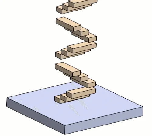
Figure 10. Solid Contact interactions.
The example above was run with the default contact accuracy settings, which bias toward solution speed over accuracy.
As a result, you can see some penetration between the blocks and the floor, excess jitter and overall, a solution that may be more unstable than reality. In most cases, this is a very solvable problem.
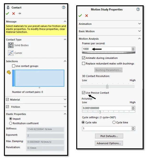
Figure 11. Contact Settings and Study Properties.
When using contact interactions, I recommend making a few key changes to the Motion Study Properties:
- Drastically increase the “Frames per second” depending on the relative speed of the contacting objects,
- And either increase the 3D Contact Resolution slider or enable Precise Contact.
These two changes can solve the majority of contact issues, but if you need to go deeper there are advanced solver options and alternate solvers that can be specified. If you’re planning on tackling complex contact problems in Motion Analysis, I’d highly recommend playing around with a jumble of blocks or spheres and doing your own experimentation with the accuracy sliders and solver settings to familiarize yourself and find a compromise between solve time and accuracy.
Depending on the type of contact, you can also save a substantial amount of solve time by defining “contact groups” instead of selecting everything globally.
Event-based Motion for Predicting Cycle Time
None of the examples so far have featured any sensor logic or sequential steps — something that’s very common in machine design and manufacturing.
You can certainly sequence various events (such as motors or actuators turning on or off) using only the Motion Analysis techniques we’ve discussed so far. But there’s also a much better method called “Event-Based Motion” which allows the definition of virtual proximity sensors, as seen below.
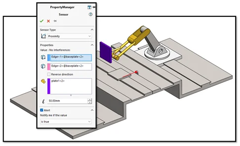
Figure 12. Proximity sensor definition for event-based motion.
Event-based motion unlocks an alternate display of the Motion Study where you can swap to a task view, which allows sequencing events, or task actions based on a task trigger such as triggering a proximity sensor or the completion of another event.
In this tutorial example, the second robot is sequenced such that it will perform its welding actions only once the stock material has moved into position and triggered the proximity sensor.
As the chain of events stacks up, this can save a lot of time (and sanity) compared to the guess-and-check method that would be necessary to try to sequence events in a purely time-based environment.
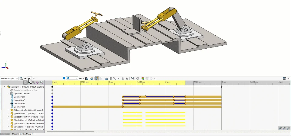
Figure 13. Event-based motion in action.
As an additional output from event-based motion you can see exactly what time each task was triggered and completed and achieve estimates of overall cycle time.
Licensing for Event-based Motion
Unlike time-based Motion Analysis (which is available in SOLIDWORKS Premium and all versions of SOLIDWORKS Simulation) event-based motion analysis requires SOLIDWORKS Simulation Professional and above software licenses.
Summary & Conclusion
With millions of SOLIDWORKS users around the world, I’d hope we would hear about Motion studies much more often. Many people have access to this tool, and either may not know they do, or may not be aware of its capabilities.
There may be some minor friction to adoption; for example, with standard mechanisms driven by assembly mates, users have to contend with appropriate mating schemes that may sometimes mean modifying or re-creating an assembly. For problems involving complex contact, users may have to explore and adjust the default accuracy and solver options.
In my opinion, these are small hurdles to overcome for the capabilities of the dynamics studies that SOLIDWORKS Motion Analysis provides. SOLIDWORKS provides built-in tutorials, so if you have access to the software, I encourage you to give it a spin and think about how and when you may use it to improve your next designs!