

Hello to all,
Welcome to the new edition of the SOLIDWORKS® Support Monthly News! This monthly news blog is co-authored by members of the SOLIDWORKS® Technical Support teams worldwide. Here is the list of topics covered in this month’s Blog:
- Understanding Color Bit Depth in TIFF, Photoshop (PSD), and JPEG Export Options
- Changing the orientation of a part while importing or inserting it in SOLIDWORKS® Design
- Sprocket chain animation in SOLIDWORKS® Composer
1. Understanding Color Bit Depth in TIFF, Photoshop (PSD), and JPEG Export Options
– Nikhil BHIRUD
When you export images from SOLIDWORKS — whether for technical documentation, presentations, or marketing renders — the Image Type you select directly determines the color bit depth of the exported file. This bit depth controls how much color information each pixel carries, affecting both image quality and file size.
Most users notice only the file format (TIFF, PSD, JPEG), but what truly defines the image’s visual fidelity is the combination of Image Type and Background / Transparency options under the Save As Options dialog.
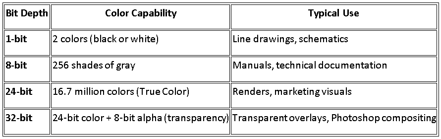
What Is Bit Depth?
In digital imaging, bit depth represents how many bits of data are used to store color information for each pixel.
- A higher bit depth allows more shades and smoother gradients.
- A lower bit depth limits the number of tones or colors, but creates smaller files.
Each image type in SOLIDWORKS corresponds to a specific bit-depth configuration behind the scenes.
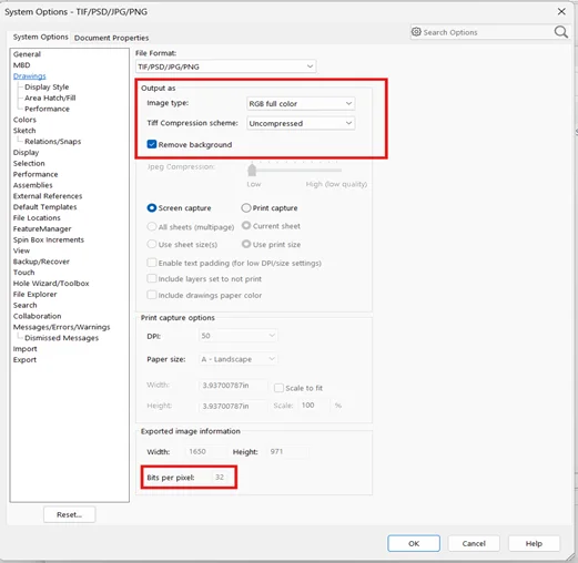
How SOLIDWORKS Determines Bit Depth
When you use File → Save As → TIFF / JPEG / Photoshop (PSD) and click Options, the Image Type setting defines the color mode and bit depth of the exported image.
You can see the resulting bit depth on the same page under Export Image Information.
The relationship between these export settings is summarized below:
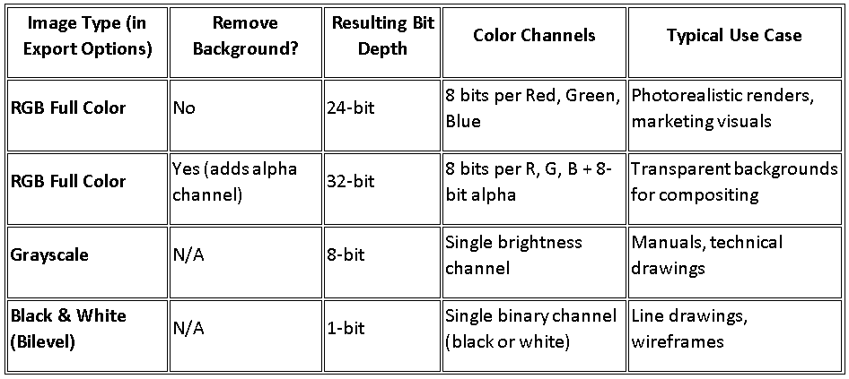
Export Settings in SOLIDWORKS
Each Image Type in SOLIDWORKS defines how colors and transparency are handled during export. Let’s look into each type to understand how bit depth affects image quality and file output.
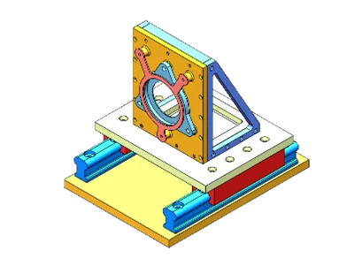
1. Full-Color (True Color) Images — Minimum 24-Bit Requirement
When saving color images from SOLIDWORKS, the software automatically uses 24 bits per pixel (True Color). Each pixel contains 8 bits for red, green, and blue combining to produce over 16.7 million colors.
✅ Recommended for:
- Shaded model views and renders
- Presentation graphics and marketing visuals
- Exports for Photoshop or print layouts
Significance: 24-bit images preserve accurate gradients, reflections, and textures while preventing color banding
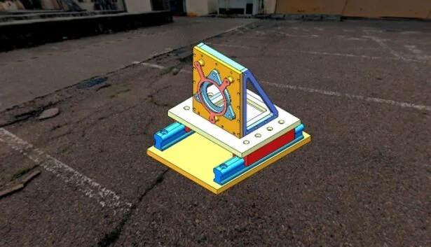
24-bit RGB full-color export maintains smooth gradients and realistic shading
2. Black-and-White and Grayscale Images — The Efficient 8-Bit Option
For technical documentation, manuals, or simple line-based exports, SOLIDWORKS supports 8-bit grayscale and 1-bit black-and-white image types.
- 8-bit grayscale stores 256 tones of brightness, giving you soft gradients and smooth shading without color.
- 1-bit uses only black and white pixels — ideal for simple line drawings, where sharp contrast and minimal file size are key.
Recommended for:
- Engineering drawings or hidden-line views
- Print-ready manuals and catalogs
Significance: Grayscale (8-bit) offers smooth tonal transitions while keeping file size small. Black-and-white (1-bit) is ideal for crisp, high-contrast line drawings on white backgrounds.
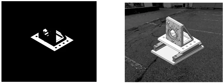
Bilevel and Grayscale Export Examples
3. Removing Backgrounds — Adding a Transparency Channel
When you check Remove background in the export options, SOLIDWORKS adds an 8-bit alpha channel to your 24-bit color image, creating a 32-bit file. This enables true transparency, ideal for overlaying models on other graphics or presentation slides.
Recommended for:
- Presentations and web graphics
- Photoshop compositing and marketing material
Significance: 32-bit images maintain full color depth and allow transparent regions — no more white boxes around parts when used in other layouts. Transparency is supported in TIFF and Photoshop (PSD) formats, but not in JPEG.
“Remove background” adds an 8-bit transparency channel for clean overlays
Conclusion
In SOLIDWORKS, every image export carries a bit-depth choice behind the scenes. Selecting the appropriate option—8-bit for grayscale, 24-bit for color, or 32-bit for transparency—helps you balance visual quality, performance, and downstream compatibility.
By understanding how SOLIDWORKS handles color bit depth, you can ensure that your exported visuals remain accurate, professional, and ready for any medium from internal reports to high-resolution marketing renders.
References: SOLIDWORKS Help – Save as TIFF, JPEG, and Photoshop Options
2. Changing the orientation of a part while importing or inserting it in SOLIDWORKS® Design
– Jayendra POTDAR
Orientation control of the part is essential for keeping neat, consistent modeling operations, whether you’re importing Neutral formats like STEP/IGES or adding native SOLIDWORKS® Design parts. To make sure the part enters your design space in the proper orientation, SOLIDWORKS Design offers a number of options, including Move/Copy Body, Co-ordinate systems, and assembly rotation controls.
Following are the ways explained in detail:
- For changing the orientation normally:
- The simplest way is to press middle button of the mouse and drag the mouse to change the orientation of the part.
- Another method is to use Spacebar and select any view in the orientation dialog, so that the orientation changes.
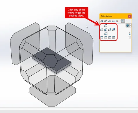
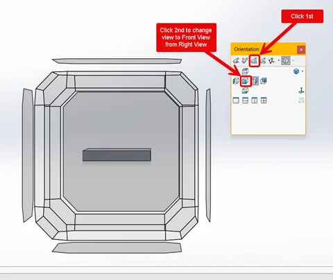
- For changing the orientation with the help of planes:
- Open the part in SOLIDWORKS.
- Press Spacebar, and click Update Standard Views and select the desired view in the orientation dialog. (Changing Front view as Right View)
- For changing the orientation with the help of planes for Neutral files:
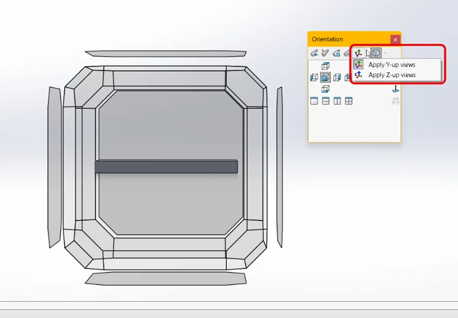
- For manufacturing/machining (Z-up):
- Open the part in SOLIDWORKS.
- Press Spacebar, and click Up Axis Flyout dropdown option in the orientation dialog.
- Select Apply Z-up views option for Z-up axis.
- Select Apply Y-up views option for Y-up axis.
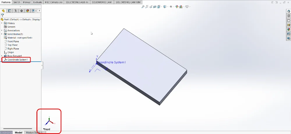
- For Y-up for imported parts with incorrect orientation (Using co-ordinate system):
- Open the imported part with incorrect orientation in SOLIDWORKS.
- Go to Reference Geometry > Click Coordinate System.
- Select a vertex as a reference point for the Position.
- Select each axis according to the orientation required. Make sure that the directions are correct.
- Click OK > Save the part as STEP file.
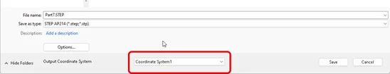
- While saving the part, select the new Coordinate System from the Output Coordinate System dropdown.The new file will now have a correct view orientation when opened.
- For manufacturing/machining (Z-up):
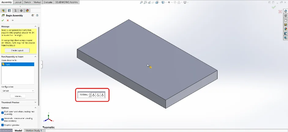
- Changing the orientation of part when inserting it in the assembly:
- Open blank assembly > Click Insert Components. After selecting the part, you can select the value of rotation of each axis individually from the Flyout Toolbar. This allows you to pre-rotate the part before you place it in the graphics area.
- Another method is to open blank assembly > Click Insert Components. After selecting the part, you can use Spacebar for orientation dialog for selecting views (Front, Top, Right).
- After placing the part, you can still Move/Rotate the part:
- Right-click the component > Click Move with Triad.
- Move/Rotate as desired.
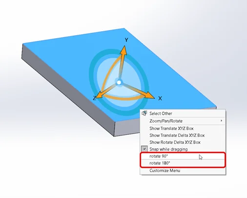
- You can also select the degree values for precise orientation (e.g., 90°, 180°) by right-clicking the Triad. Make sure the part is not fixed while performing Step 4.2
- Open blank assembly > Click Insert Components. After selecting the part, you can select the value of rotation of each axis individually from the Flyout Toolbar. This allows you to pre-rotate the part before you place it in the graphics area.
- Use Move/Copy Body after the part is inserted:
- Open part in SOLIDWORKS.
- Go to Insert > Features > Move/Copy > Scroll down to the bottom and click Translate/Rotate.
- You can insert the values for moving and rotating the X, Y and Z axes as desired. You can find more information for the topic in the following SOLIDWORKS Design Help link
Conclusion:
It is always recommended to select the orientation and placement of the part before inserting it into the graphics area. This will help resolve most of the orientation issues.
Happy Designing!
3. Sprocket chain animation in SOLIDWORKS® Composer
– Prajakta LIMBASARKAR
We all are aware about the sprocket chain mechanism in SOLIDWORKS. We can define sprocket and chain in the Belt/Chain Assembly feature. However, we do not have same feature in Composer.
There are many methods to create sprocket chain animation. In this blog, we can learn methods to create a Sprocket Chain mechanism animation in SOLIDWORKS Composer by Method A: Highlighting each chain.
Method A:
In this method, we rotate the sprockets whereas, highlight each chain. Making it appear to be moving.
- Import an assembly file of chain and sprocket in Composer
- Move time bar to the 3 second> select Sprocket> Transform> Rotate> rotate the sprocket 360 degree.
- Follow the step 2 for the second sprocket as well.
- Move time bar at 0 second > select an inner chain actor> Timeline> effects> Hot Spot> notice the select actor is highlighted for 0.3 second.
- Move time bar to 0.3 second> Select the adjacent chain> assign Hot Spot effect> notice the second chain highlight as first chain is ends.
- Follow the same procedure for all the chains.
Below are the final results.