
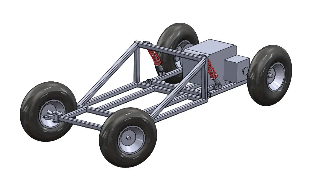
In the previous part of this blog series, I used SOLIDWORKS for makers to design the rear portion of the kart chassis, this incorporates the engine mounts and suspension mounts. Now it was time to start working on the forward portion of the chassis, I’d be using similar tools to the previous blog but on a larger scale as the forward chassis needed to be able to support the weight of the rider along with the upper suspension mounts and forward axles for the front wheels.
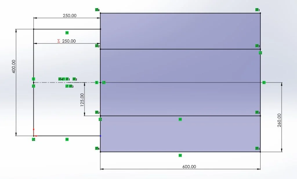
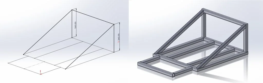
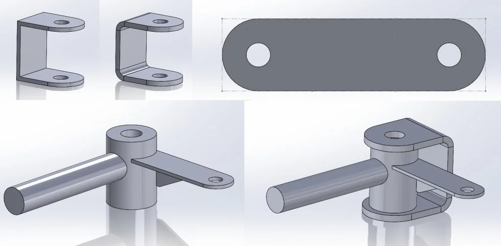
I started again by using the weldment tool to quickly sketch out some upright pieces of square tubing which would act as the upper mount for the shock absorbers, I’d use the same folded mount design I created and used in the previous section of this blog series. I expected there to be some force applied to these vertical members so my next decision was to add some 45degree bracing pieces away from these which would help to absorb the forces being applied to prevent the frame bending at this contact point. I also sketched out some horizontal pieces which would act as the main side rails. Once this sketch was initially completed, I used the Weldments tool to create a frame from 30mm square tubing. At this point I wasn’t concerned about tube end preparation and intended to go back to this later in the process.
From here I needed to add supports for some sort of seat, model and decide where to attach the front steering axles and add some extra bracing in a few areas to ensure the frame was ridged enough to support the weight of the rider and the day-to-day shocks introduced through use.
I set about first creating the cross rails which would support the seat, I had a rough idea how far apart these needed to be after taking some rough measurements from the seat unit I’d acquired. I went back to my original sketch used in my first weldment feature and edited this to include another couple of lines which would act as these seat support bars. Whilst in this sketch I added an additional cross brace at the upper suspension mounts and the lower corner, this would provide sufficient stiffness and support for use. I then another at the front of the car to complete the frame shape, there was a chance I’d again need to go back and edit this sketch, but I felt this was a good starting point.
I started another assembly adding the upper suspension mounts onto the created frame. From here I needed to model the front axle assemblies. I started by creating a part for the axle stub using a couple of simple extrudes and reference frames to mirror the part I had in hand. From here I needed to create the sheet metal mounting portion of the axle stub assembly to use as the welded mounting to the chassis frame. I followed the same method as the previous blog, creating a solid body part before using the “convert to sheet metal” tool to quickly turn my solid body into a flat sheet metal part with the correct bend radius.
With the axle assembly completed I could start to finalize the main chassis assembly; I first added the chassis before adding the front axle mounts and stub assemblies. One point I wanted to check here was that the control rods for the front steering axle would clear the frame material. If this was not the case, we’d be unable to steer the kart. Luckily everything lined up and the clearances were correct on the first attempt. To finish this portion off I created one new main assembly before adding the rear chassis and main chassis assemblies together, attaching with the mounting points and suspension components as I would in the real build.
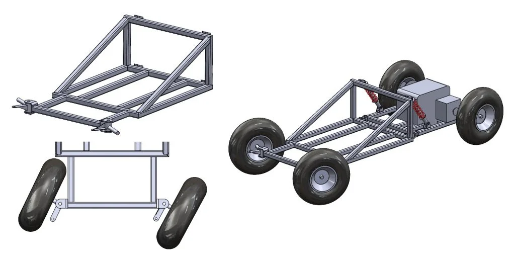
I really enjoyed this portion of the project, I could now see everything starting to come together and knew it would shortly be time to start making! I decided the next portion would be to design the steering system, check back soon for that blog.