
In my last blog I showed you how I used SOLIDWORKS for makers to make some rough models of some components I’d managed to scavenge or buy for my latest project! In this blog I’ll be showing you how I used these models and some basic SOLIDWORKS design tools to create the rear portion of my ride on offroad kart including the rear suspension, engine mountings and rear axle assembly.
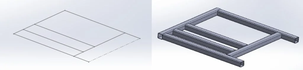
I started this portion of the build by creating a simple sketch with the 4 mounting hole positions for the rear axle, this gave me some strict geometry I needed to support with metalwork. From here I headed to my toolbar to load up weldments. Now I’m very open and say I don’t use weldments anywhere near as much as I should, some of this comes down to the majority of my day job not focusing on sheet metal or metal framework but some of it also comes down to laziness. However, I figured as I was writing a blog I’d show off how easy it can be to pull together framework models using weldments and some of the simple tools within it.
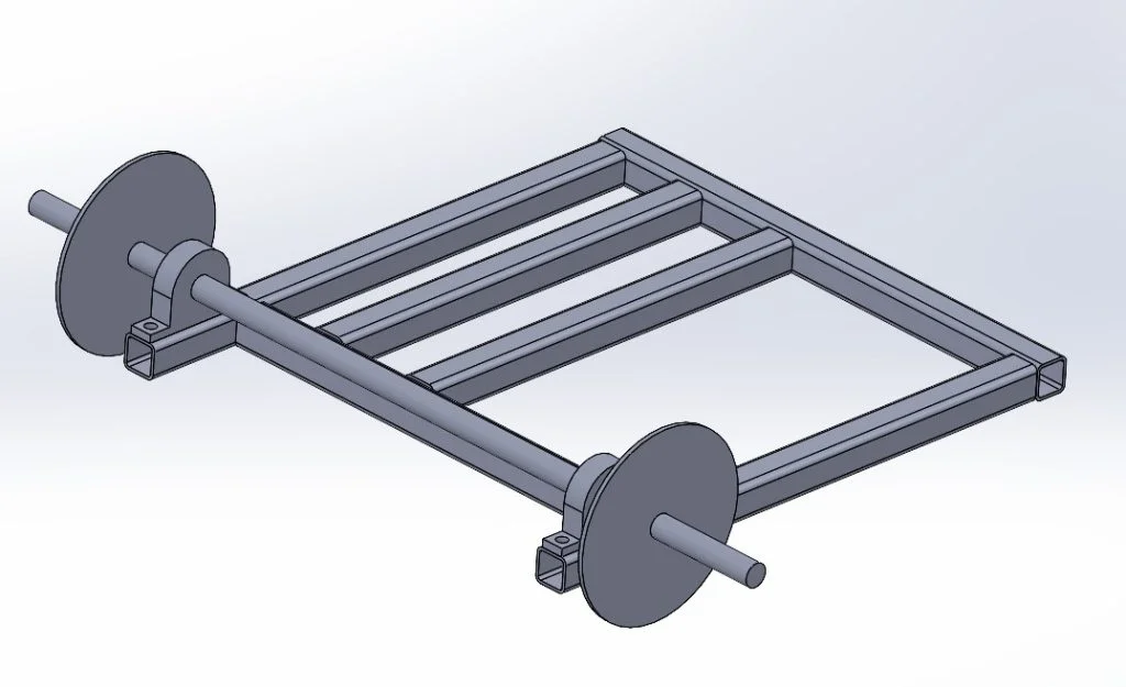
Weldments has an awesome tool called structural member which lets you convert 2D and 3D sketches quickly into a long list of standard structural steel sizes such as channel, round and square tube across a range of ANSI and ISO standards. This amazing tool made it really quick to throw together a frame design based around the mounting points of the rear axle. I used the same tool again to add some additional framework to sit underneath the engine to secure this too. When designing this portion I took care to ensure the output sprocket of the engine was lined up with the input sprocket on the axle.
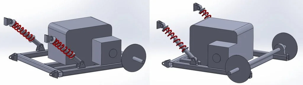
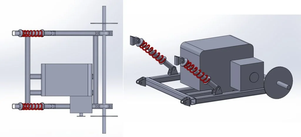
From this point I decided it would be best to start a new assembly to start to build up a view of what this rear section would look like, this helped to give me a view of where parts may clash and where would be best to mount my suspension springs to. I used simple coincident mates to connect thru holes in the motor mounts to the chassis and the same type of mates for the rear axle assembly.
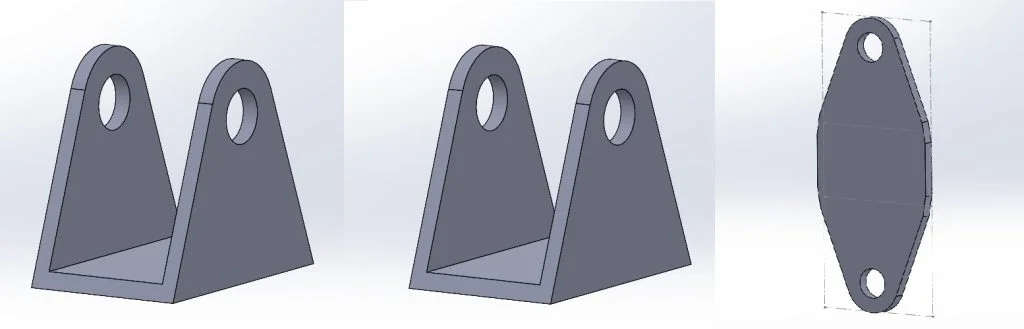
At this point I knew I needed to design some simple mounting points for the end of the suspension to bolt through. Again, I figured I’d challenge myself to use some basic sheet metal tools. I sketched out my part before using the extrude tool to add some length to the mounting channel before using another sketch and an extrude cut to remove some material and add some more shape into the design. From here SOLIDWORKS has some amazing tools to first convert this design into sheet metal form using the “convert to sheet metal” tool which allows you to specify the material gauge or sheet thickness, add bend points and adjust bend radius. This tool quickly allowed me to convert a 3D body into a piece of sheet metal which could be manufactured. SOLIDWORKS had another trick up its sleeve when it automatically processed this design into a flat pattern allowing me to export and save this as a DXF for cutting.
From here I began to make an assembly showing how the new created frame, mounts and procured components would go together. I could then use this assembly to check sprocket alignment and fitment of thru holes to mounting plates. This assembly could also be used in the next step of this project to create the main chassis portion from.
This portion of the project was great fun, it made me think outside of my usual tool selection and advanced some of my use of sheet metal and weldment tools. SOLIDWORKS has a great selection of toolboxes which are tailored for ease of use depending on the work you’re doing. For the next portion of this blog series, I’ll be focusing on the forward chassis and how this connects to the rear assembly we’ve designed in this blog. Check out the video below to follow along with the tools used in this blog.