What’s New in SOLIDWORKS xDesign R2025x FD03
Your favorite browser-based solution, SOLIDWORKS xDesign, is introducing some exciting new enhancements this month! The latest functional delivery (FD) update, R2025x FD03, includes:
- 2D Authoring for Section and Detail Views
- Generative Drawing Views
- Enhanced Control for XR Design Review
- Generative Hole Callouts for Non-Native Geometry
- Convert Image to 2D Mechanism Option
Let’s have a look at what’s new in this release.
PART & ASSEMBLY DESIGN
Convert an Image to a 2D Mechanism
Convert an image of a mechanism into a sketch with the new 2D Mechanism option in the Picture to Sketch tool. This option uses logic to recognize objects in the image, such as straight linkages, linkages with slots, bent linkages, fixed anchors, and rollers, to convert them into sketch objects. It also recognizes constraints in the image, such as hinges, sliders, and anchor points, to convert them into sketch constraints.
This command works best for converting a screenshot of a mechanism in a textbook into an editable 2D sketch.
Enhanced Control for XR Design Reviews
In our last release, we announced the new Extender Reality (XR) functionality, which enables you to visualize your product in a virtual or real-world environment using new virtual reality (VR) and augmented reality (AR) settings.
Explore and understand designs more effectively when visualizing designs in VR and AR with new ways to interact with your model. The Grab Skill now supports rotating, scaling, and pinning components in place. Additionally, with the new Hide Skill, you can selectively hide assembly components and then Show All Components when you want to see the complete picture again.
Improved Measure Tool
Quickly inspect and verify geometry to ensure accuracy and design intent with enhancements to the Measure tool. Updates include the ability to hide measurement flags, view maximum dimensions, and clear selections from the right-click menu. There’s also a new mini dialog that’s optimized for small viewports.
Design in Context with Custom Environments
There’s a new option to create your own custom environment and insert it into your design. Using the Create Environment tool, you can easily create custom user-defined design environments to contextualize your models.
Using design environments allows you to design in the context of a larger model while maintaining high system responsiveness. It’s also nice if you’re going to create a rendering of a product and you want to include it in its natural environment to show its intended use.
SUBDIVISION MODELING
Align to Sketch Proportional
In the subdivisional modeling workflow, we’ve added what we call a proportional alignment capability that you can access in the Align to Sketch feature.
This enables you to quickly create complex shapes that closely capture user input by creating a proportional alignment between mesh entities and your sketch.
How it works is you select your vertices/mesh entities, then use the Align to Sketch tool to draw a line manually, then you can enable the Proportional setting that distributes the vertices along the sketch while keeping the original spacing.
DRAWING & MBD
In this update, we’ve done quite a bit to enhance xDesign’s definition capabilities.
2D Authoring – Section & Detail Views
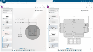
Now you can create detail views and section views in 2D. Previously, you could only create the section view in 3D and then place that view on the drawing, so you were only able to use MBD workflows to create sections and details.
Now you have the classic 2D drawing workflow that many engineers are familiar with, so you can place the section line and create a section view directly from your drawing sheet.
With the ability to create section and detail views directly from the drawing environment using traditional section lines and crop circles, you can ensure a clear interpretation of the drawing. The section lines and crop circles are automatically shown on the parent 3D views to improve model-based communication and reduce the model-based learning curve.
This enhancement gives you a single source of truth and the ability to see parent-child relationships across different views using both 2D and 3D.
Generative Drawing Views (BETA)
Use the power of artificial intelligence (AI) to eliminate repetitive drawing tasks with generative view creation and placement. In the new Sheet Command, there’s a new option called Generate Drawing Views (Beta).
During sheet creation, you can generate drawing standard views, such as orthographic and isometric directly from the 3D model with minimal manual input.
When you enable Generate Drawing Views it will automatically review your model and create all of your standard and orthogonal views and isometric views, saving you time from having to manually create the views. It will correctly scale them to your sheet and correctly position them as well.
Generative Hole Callout
The Hole Callout command has been enhanced to automatically create comprehensive callouts for all types of geometry, removing the need for holes to be created with the Hole feature in xDesign. This expands the detailing flexibility by enabling quick, accurate dimensioning of holes on imported or legacy data, as you can create precise hole callout annotations on native and non-native geometry, such as imported STEP or SLDPRT files.
Using AI, hole callouts are automatically generated using actual geometry, so you can create a hole callout for any cylindrical shape. The software will look at the geometry to determine if it’s a simple hole, or counter hole, for example, and then automatically create a hole callout.
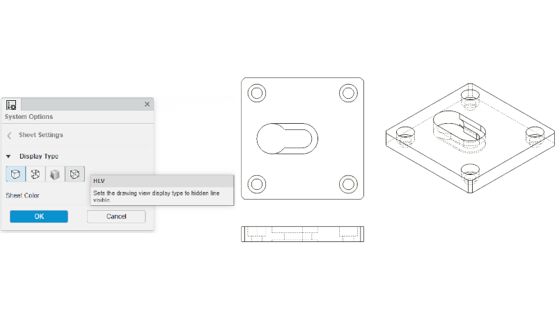
Hidden Lines Visible (HLV) Mode
This update also adds the popular industry format, Hidden Lines Visible (HLV) mode, a display mode that shows the edges of features obscured from view by solid geometry as dashed lined in 3D and 2D.
This will enable you to clearly identify internal or hidden geometry without sectioning the model, thus simplifying the drawing, while enhancing clarity for downstream communication.

Enhanced Placement of 3D Annotations
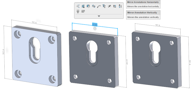
Ensure your 3D annotations are always readable with new annotation flipping options. When defining your model in 3D, annotation and dimension text can now be flipped horizontally and vertically to ensure readability from alternate viewing angles. This is especially valuable when reorganizing annotations for different model orientations, such as moving a dimension from the front to the back view.
Furthermore, the new flipping options will ensure clarity and readability in all contexts and eliminate the need to recreate annotations in the new desired view.

3DPlay Support for Section, Detail, and Flatten Views
3DPlay now supports the ability to view native annotation sets with model-based section, detail, and flatten views.
Easily take a physical product or annotation set and drop it into 3DPlay to view the content and collaborate downstream with stakeholders.

RENDERING
Multi-view Rendering
Effortlessly generate stunning renderings of multiple views with a single click. The Render Image dialog is now capable of rendering multiple views in one step. These can include the current viewport or a custom selection of predefined camera views within the rendering environment.
This enables you to publish multiple renderings at the same time. For example, if you set up a project with multiple scenes and you go to publish, you can now select all the different cameras and scenes that you want to publish, and basically do a bulk render, instead of having to do each one individually.
In addition to the enhancements above FD03 also includes the following updates:
- Added the option “Show Feature in Design Manager” in context menus and breadcrumbs, which expands the entire parent path and auto-scrolls to the selected feature in the Design Manager.
- Added a “Refresh” command to the context menu for SOLIDWORKS components that will bring the latest version of the component from the database into the session.
- Added the ability to send an unlock request to other users when using the Unlock command on the Lifecycle tab of the Action bar for a component that is locked by another user.
- Added a Flip button to the Edit Sketch Plane dialog to correct issues where the sketch flips in the wrong direction, resulting in downstream errors.
- Added the ability to pin the Session Information panel to the right side of the session.
- Improved performance and accuracy of dynamic and selection highlighting in the graphics area.
- Improved the logic for expanding sets when activating or expanding components in the Design Manager.
- Improved the Sweep command with the Up To Geometry end condition so that the end face is tangent to the reference geometry and improved assigning face IDs for a sweep feature, so the faces are referenceable in downstream operations.
These enhancements are available starting July 5th.
We’ve also got some enhancements specific to the SOLIDWORKS xDesign for Students and 3D Designer for Education editions. Stay tuned for the blog coming soon on the SOLIDWORKS Education Blog.
Check out the last update, FD02, in this blog here. And visit the What’s New page to learn more about FD03 updates.
One last important note is that the SOLIDWORKS xDesign Offer will now include a new single combined SOLIDWORKS xDesign role instead of a package of separate roles. Not to worry, because the offer will still include all your favorite tools for parametric modeling, subdivision modeling, sheet metal, 2D drawing, and MBD, structure design, mold design, and rendering.


