Growing up and playing with LEGO® as a budding engineer, had you ever thought about how strong your LEGO® pieces were? We shall investigate this thought using SolidWorks Simulation, an FEA module that runs natively within the SolidWorks User Interface. We will use modules that are available in the Simulation Premium package to illustrate the full extent of SolidWorks Simulation capabilities to see not only linear behaviour, but also the non-linear behaviour of our LEGO® piece and determine, is it as strong as we think it is? For those parents frustrated with LEGO®, keep reading and see whether you have the strength to deform and “take care” of them for good…
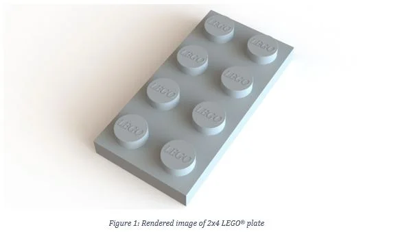
We decided to investigate the strength of one of the most common pieces, a 2 x 4 LEGO® Plate, and also highlight the user-friendly SOLIDWORKS Simulation capabilities.
The aim with simulating a 2×4 LEGO® plate was to estimate how much force it could take to misalign the studs such that it becomes incompatible for other LEGO® elements to stack on it. From measuring and experimenting samples of a 2×4 LEGO® plate with other pieces, we realised that some of the tighter fits between pieces were when the stud spacing deviated 0.1mm from nominal dimensions. To note, assumptions have been made especially where access to exact information is limited (e.g. Material data).
ASSUMPTIONS
- Permanent deformation of greater than 0.2mm between the studs will render them incompatible/un-stackable
- LEGO® bricks are made of ABS Plastic (Injection moulded grade), however, the ABS that is used is not public knowledge. Instead we extracted the Yield and Ultimate Tensile stress from literature*(Doraisamy & T, 2017) and thus, estimates generated here may be lower than what the original product may withstand.
- The LEGO® piece is constrained in the y-direction as it is stretched axially in the x-direction – i.e. assuming a perfect clamp/fixture pulling in one direction like in a tensile test. This is to stabilize the FEA model in the y-direction.
ANALYSIS
For the analysis, we simulated a quarter of the 2×4 LEGO® plate, taking advantage of this piece’s symmetry (shown below):
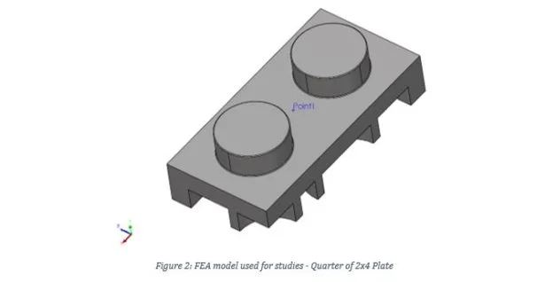
Figure 2: FEA model used for studies – Quarter of 2×4 Plate
The first step taken in this investigation was to see if by chance, an average adult would be able to pull and permanently deform the LEGO® plate while gripping either end.
The following inputs were used:
- The adult pulls the piece as per the perfect clamp assumption
- The adult is male, sitting down, forearm horizontal (viewed from the side) and pointing at the 12 o’clock position (viewed from the top) and according to Das and Wang (2004), the total average pull force with the right hand under these conditions is 208.97 N. Input is half that for the quarter model used in the study and force is assumed to act equally (same force magnitude on the left side).
- Assuming a thumb and index finger grip, from literature(RIT, 2006), the grip strength is on average 19 lbs. For the input, it would be 9.5 lbs.
With all these assumptions and inputs translated into a linear static study, the resulting displacements and von Mises stress is shown below:
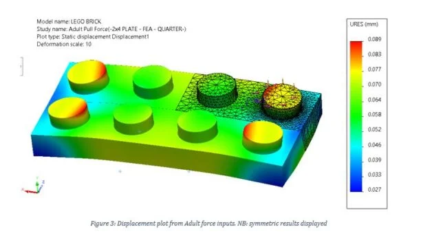
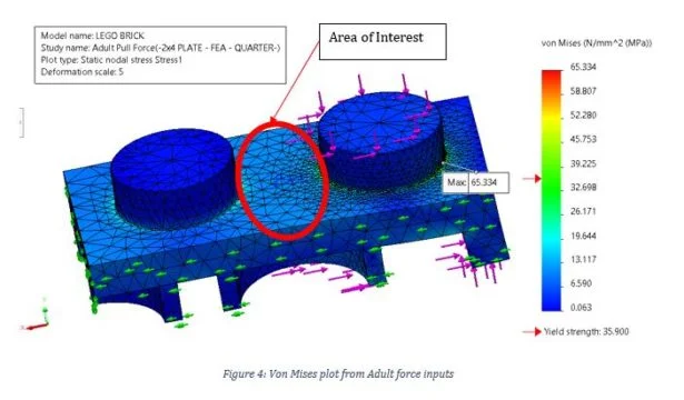
The area of interest for us is the region circled in red shown in Figure 4. Based off the colour chart, the region hasn’t permanently deformed as the majority of the area is well under yield, and at the same time, the max resultant displacement is not at all close to 0.2mm (Assumption 1), thus, we can confirm an average adult wouldn’t be able to render this LEGO® piece unusable.
From here, instead of trying to iterate by inputting a force until we reach both yielding in the area of interest and getting the stud spacing displacement to be >0.2mm from nominal position, an analysis was setup that answers the question: What is the axial force that will cause the piece to deform to 0.2mm when pulled? This will serve as the minimum condition for the piece to fail.
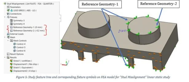
With that said, another Static study, called Stud Misalignment, is made where the external loads are replaced with two Reference Geometry fixtures:
1.“Reference Geometry-1” represents an idealized grip (like a vice grip, but does not induce any loads on the component) that stabilizes y-direction
2. “Reference Geometry-2” which replaces the “PULL” load into a prescribed displacement (acting in the same direction as the force) of 0.2mm. Sim feature tree for this study below:
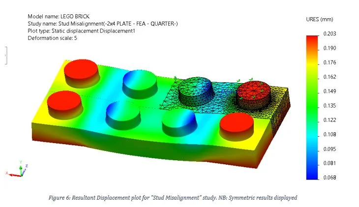
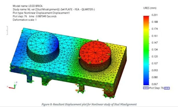
The corresponding displacement and von Mises stress plots were made:


Because there is plasticity in the region circled in grey in Figure 7, The static study was copied into the Non-Linear analysis module to double check the stress distribution around the area of interest. This is because linear static analysis does not capture stresses accurately at or past yield because of the stiffness inherent in the linear static solver. The corresponding displacement and von Mises plots are shown below:
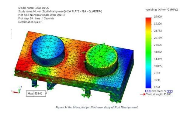
The von Mises stresses now read lower magnitudes, especially at the area of interest highlighted in Figure 7, and are awfully close to yield, but the stress distribution is the same. From this, the next thing to do is to make a plot showing stress in the x direction (Figure 10). The reason is so we can find the minimum axial force we will use as input for a Design Study.
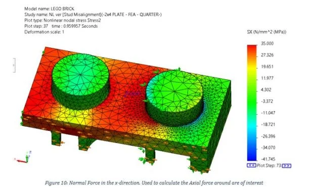
Cross section dimensions at the area of interest as shown in Figure 7 is 1.5mm x 7.9mm and the maximum stress experienced around that area is approximately 35MPa (based on the colour chart).
From equation:
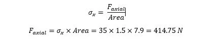
The axial force is 414.75 N. The reason for finding the axial force was so that we know what the lower limit the loading needs to be to ensure that the LEGO® piece is stretched to 0.2mm.
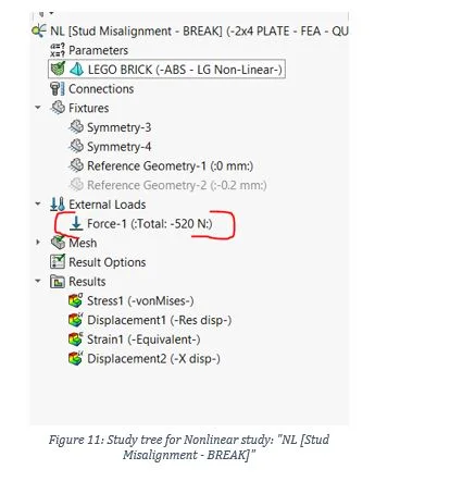
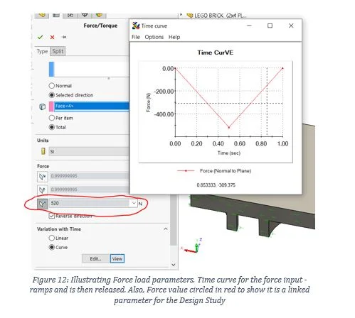
The “STUD MISALIGNMENT” study was copied into a different non-linear study called NL [Stud Misalignment – BREAK]. The “Reference Geometry-2” fixture was supressed and was replaced with a force load for the pulling force (Figure 11). This force was made into a parameter for the Design study and will take any value greater than 414.75 N. Also, this load has an associated time curve to it to see if the residual displacement will be at or more than 0.2mm. (See Figure 12)
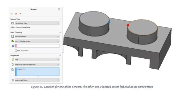
The Design study is used to help find what force is required such that its residual displacement is at or greater than 0.2m. To aid in the Design Study, two sensors were placed, shown in the image below (shown with the dots):
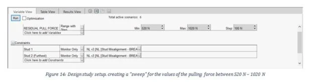
There was a total of two Design Studies run. The Design Study tried to help find the magnitude of the pulling force needed to have a residual displacement of 0.2mm between the studs away from nominal position. The first run was between 420 N and 520 N and that range of force magnitudes were not close to satisfying the aim. Figure 14 shows the next run, with the range between 520 N to 1020 N as inputs to determine the pulling force that satisfied the aim of the study.
CONCLUSION
Going back to the aim of this investigation; what would it take to make this 2×4 LEGO® Plate unusable? And do parents have the strength to deform there kids LEGO® pieces?
Well, after going through the Design Study data, the force that will satisfy the aim of this investigation is approximately 920 N.
This would mean that it would take roughly more than 4x the strength of the adult referenced in the very first linear static study to be able pull this piece to create a permanent deformation of 0.2mm and make it unusable. Sorry to the parents frustrated with LEGO® out there, but it’s way stronger than you! You’d definitely need a machine to take your frustrations out on this.
This force value was found by probing the 2 vertices where the two sensors are located for the x-direction Displacement plot. Each respective probed node will show how far it has been displaced from its original position and taking the difference between them would give the value of their misalignment, which the aim set at 0.2mm. See Figure 15.
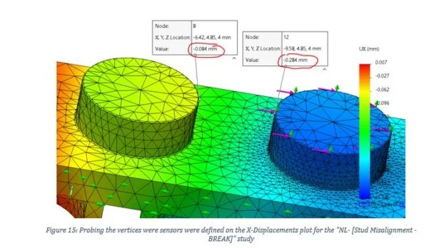
From these measurements and using absolute values (since both nodes moved in the same direction)

Looking back at this investigation, hopefully you are able to see that SolidWorks Simulation provides the tools necessary to create design validations, from serious designs for expensive projects, down to light-hearted and fun products for all ages such as LEGO®. It is straightforward to copy across studies from the linear elastic module to the non-linear one and on top of it all, integrating a Design Study that uses already made studies in helping us search for quantities that we needed.
If you have any questions regarding the investigation done in the blog, or wanting to contact us about SolidWorks Simulation or other SolidWorks products, do not hesitate to reach out to our team at CADspace.
DISCLAIMER:
Please bear in mind, the ABS used for this investigation is quite soft compared to what LEGO® reportedly uses, so the LEGO® plate will more than likely survive this type of loading, but at least we know that it would take more than what this study found
*Material Parameters was extracted as per reference source for ABS. Parameters were: Yield Stress = 35.7 MPa, Tensile Stress = 37.9 MPa. Von Mises Plasticity model used Stress-strain curve between Yield and Tensile Stress extracted from provided graph
Written by Marlunn Oducayen, CADspace Application Engineer