
During part 1 of this blog, I showed you how I used the powerful SOLIDWORKS for Makers to design my dog’s own soundboard to allow him to communicate with us more easily.
If you haven’t read part 1, I suggest you start [HERE] before reading on.
In part 1 we completed the design work for the soundboard we’d be making, I decided to split this blog into 2 parts due to the length of the designing part. The image below shows the design I came up with and once I’d completed this design work, I sent these off to a local 3D printing bureau to have these printed in Nylon using SLS technology. I also decided to have the base dyed black and the top dyed blue.
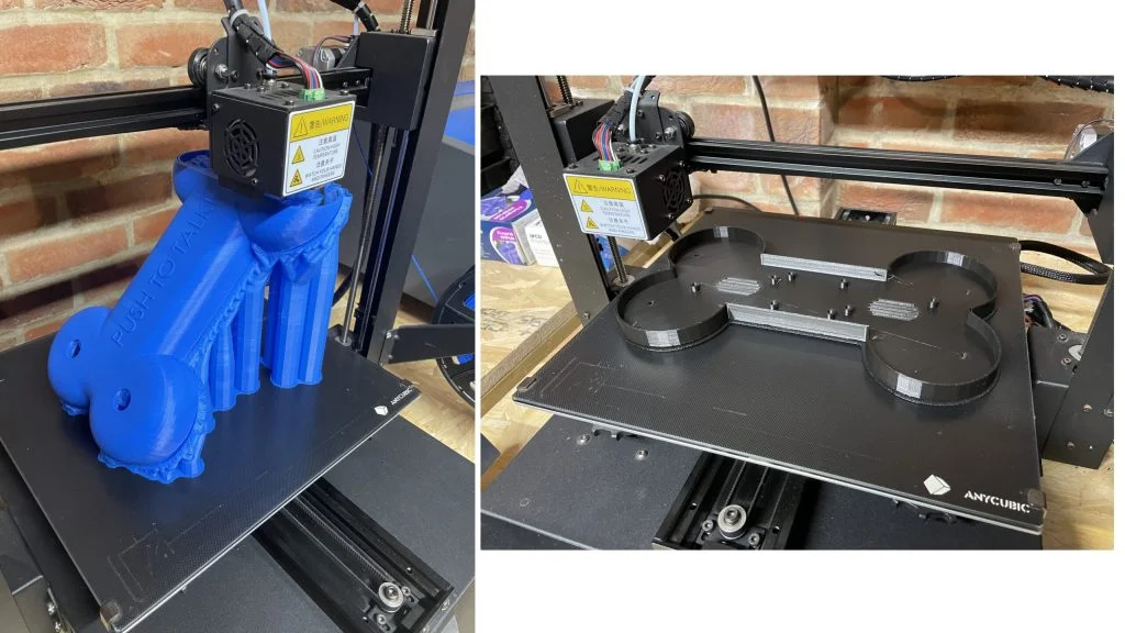
After a week or so a package landed on my doorstep full of the 3D printed versions of the components I had designed, by choosing to have these dyed by the supplier I’d saved myself the need to sand, prepare and paint these. Great news as I openly and passionately say how little I enjoy sanding and actively find any way possible to avoid doing so. The supplied prints looked great, the next step for me to complete would be to insert the heat set inserts into all the required locations. These inserted metal threads would be used to hold electronic components in place and also the upper and lower casings together. To use these inserts, you need access to a soldering iron, set to a high heat and wait until reached. At this point it’s a very simple but somewhat fiddly at times process, place the insert into the position you want to sink it into, apply the end of the soldering iron too it. As the heat transfers to the insert the plastic around these beings to melt, at this point push gently down and watch it sink into the 3D printed material. After inserting what felt like 100 inserts but was probably only 15 or so I could begin to start the assembly of the housing and electronic components.

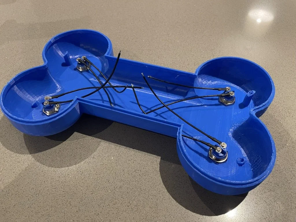
For the assembly I started with the upper casing, I inserted each of the three mushroom buttons through the cutouts within the design. The push buttons came with a securing nut which I wound into position from the inside of the casing, giving a small nip up with an adjustable spanner being careful not to crack the plastic casing. Once these were in position, I needed to add a positive and negative wire from each which would route back to the control PCB. To do so I cut 3 lengths of Brown and Black wire to a length of 150mm, I stripped both ends using and handheld wire stripper, once stripped I attached one pair of wires to each button securing using a screwdriver to fasten the terminals securely.
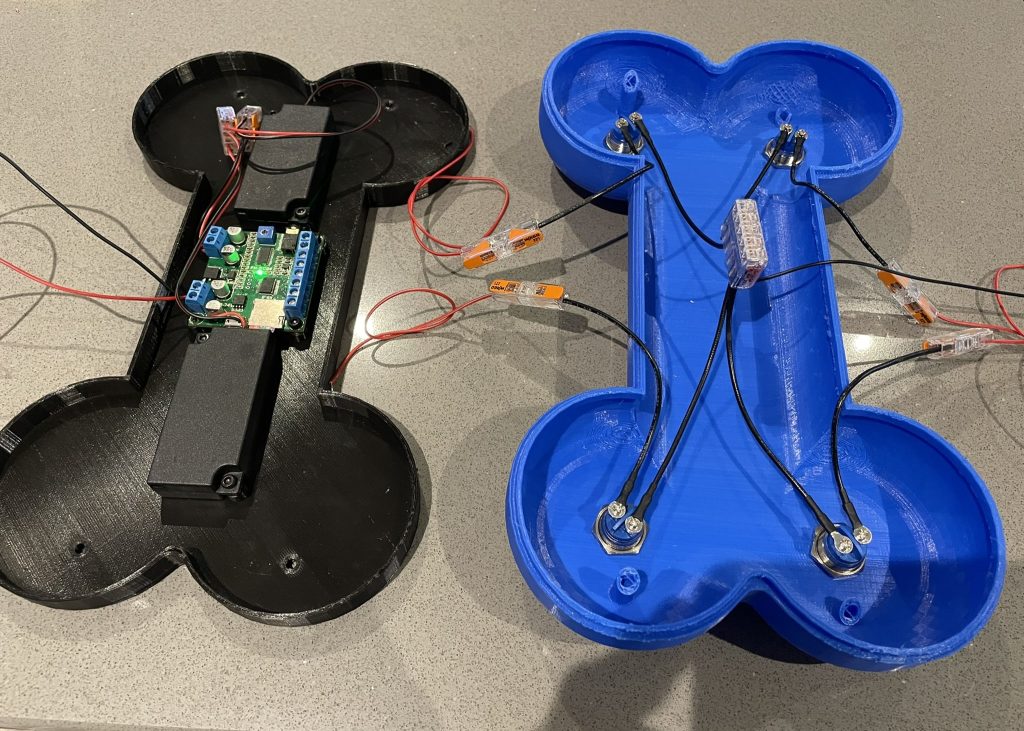
The lower casing was slightly more complex, I needed to install the control board, battery pack and speaker modules. I followed a simple process of lining up each with the mounting positions we had designed in part 1, the heat set inserts make it dead easy to effectively secure each component into position. If I’d elected to use simple self-tapping screws there’s a good chance, I’d strip the hole and have no way of rectifying the issue easily, for this reason I use these inserts a lot within my design work. With all the components mounted in the lower housing it was time to start wiring up the system.
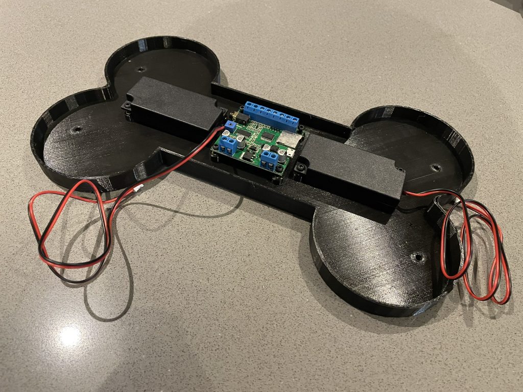
I first had to wire two small 6V battery packs together in series to create the required 12V voltage value needed for the soundboard PCB I was using. The circuit board calls for a voltage between 9 and 24V and as I already had a couple of 6V packs small enough to fit within the housing I elected to wire these to create 12 volts. Once this was done, I wired the speaker module into the output terminal on the control board, this is as simple as wiring the battery in, red wire to positive and black wire to negative. With the lower components now wired I used this stage of the build to add the selected sounds, the design on the circuit board uses a micro-SD card with up to 4 sound files preloaded onto it. It’s a very simple process, essentially drag, drop and rename your 4 chosen files to match the required format.
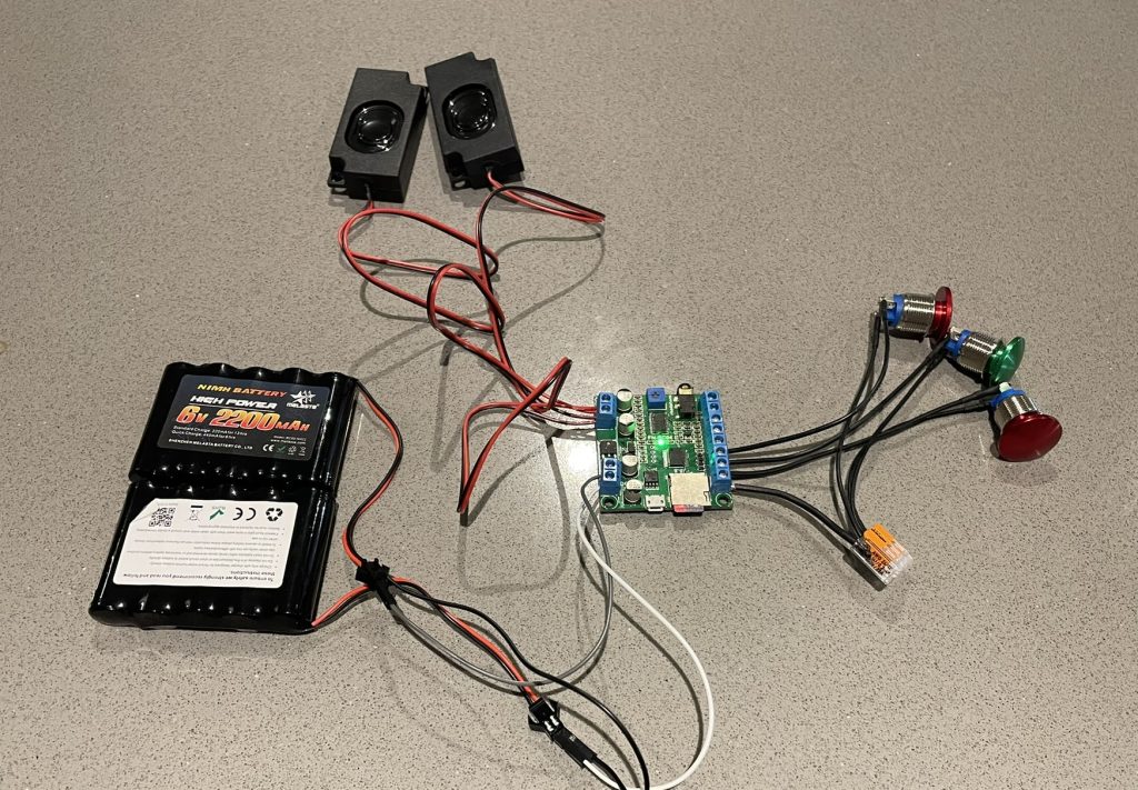
With the upper and lower sections now wired independently of one another it was time to connect these into one testable circuit. I firstly needed to connect all the push button negative wires together to make it easier to connect this back to the single negative return terminal on the PCB. I use a connector block to connect the 3 wires together and then used a short new piece of black wire to connect this block to the negative terminal on the board. This is a far better way of making these multi return connections to ground or neutral than shoving 3 or 4 wires into one small screw terminal on a PCB… I always find when people do this one wire isn’t secured properly and quickly falls out. From here I wired the brown positive wire from button 1 to the K1 terminal on the PCB, Button 2 to K2 and button 3 to K3, simple! With those connections made the system was functional!
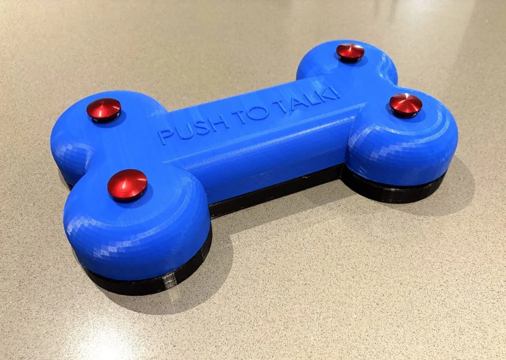
I placed the upper housing on top of the lower taking care to ensure all wires were tucked inside. Holding securely, I flipped the unit over and began to secure using 4 screws aligning with the heat inserts we’d installed earlier. With the screws securely fitted and the unit now joined together I removed the backing from some small rubber feet and positioned these into the small counterbores I’d designed to accommodate these. These rubber feet would not only stop the unit sliding around on hard floors but would also stop any noise or movement when in use. With these in place the unit was complete!
Thank you for following along with this 2-part project, this method and electronic system can be used for a range of projects, I’d love to see some of the other applications our readers can apply this to!
Check out the making video below.