
The design of this cogs toy originated from my other tutorial here, click the link if you’d like to see how it was designed and modeled in SOLIDWORKS.
I started with the assembly of my design open. Then selecting file, I could select ‘make drawing from assembly’. The first thing I had to select is the sheet format and size, for this I used my own custom saved drawing sheet, selecting browse I could open my A2 custom drawing sheet.
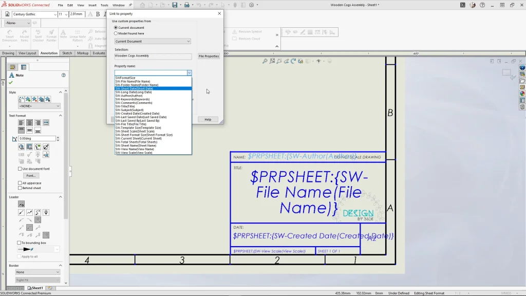
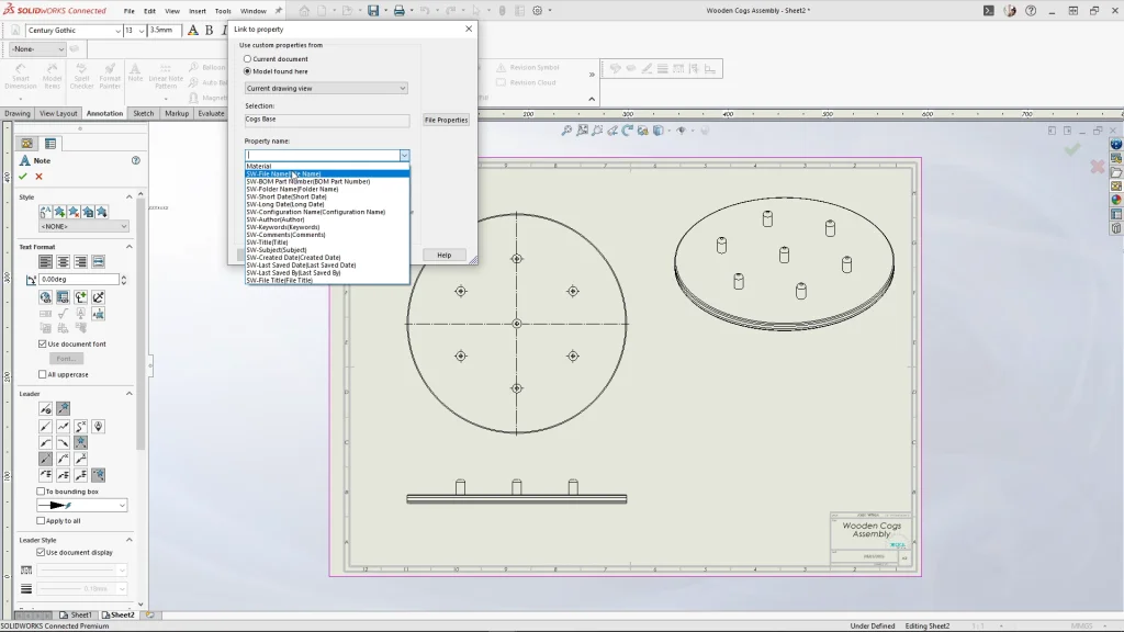
Before I inserted any assembly views, I wanted to demonstrate how to edit your sheet format and also show how my custom drawing sheet has pre-input custom properties. So, when I bring in drawing views the drawing sheet will update with the files name, creation date and view scale. These were all created using a note with a link to property feature, you are able to choose from a list of properties seen below. Once you have your drawing template you can use save as to save it as a sheet format to use for future drawing sheets.
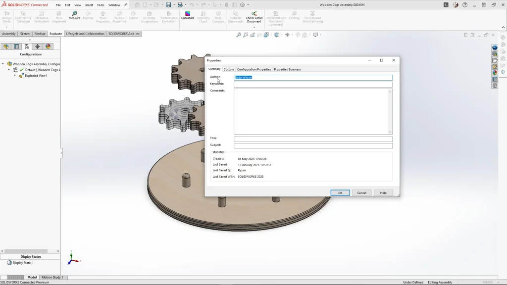
Under the view palette, you can browse for the part or assembly you need, and you can then drag views onto the sheet. After dropping in the view, my drawing sheet will update with all the details. If you want the author’s name to be visible, the information needs to be added to the assembly’s file. Going back to the assembly of the toy, I selected file properties and the summary tab. Here you need to type in the name of the person who created the file and apply it.
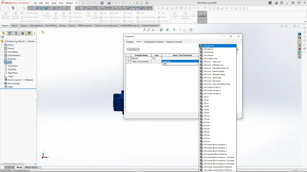
Next, I added the all important bill of materials table, I decided to change the description column to materials. Double clicking onto the C title bar I could change the column type, I kept the drop-down as custom property and the property name is changed to material. You will see that all of the column updates with each parts material names. For this to work you need to have assigned materials to each of your part files. I demonstrate how to apply the material property to the part in the tutorial. Opening the 3D printed cog, you’ll see that I had a PLA material applied to the cog.
Under properties, there is a custom tab, here you can add new properties to parts which can then be added to your drawing sheet. Under property name I can select material, then in the value/expression column, under properties I needed to select the SW material option. This will then insert the applied material information to the part files properties.
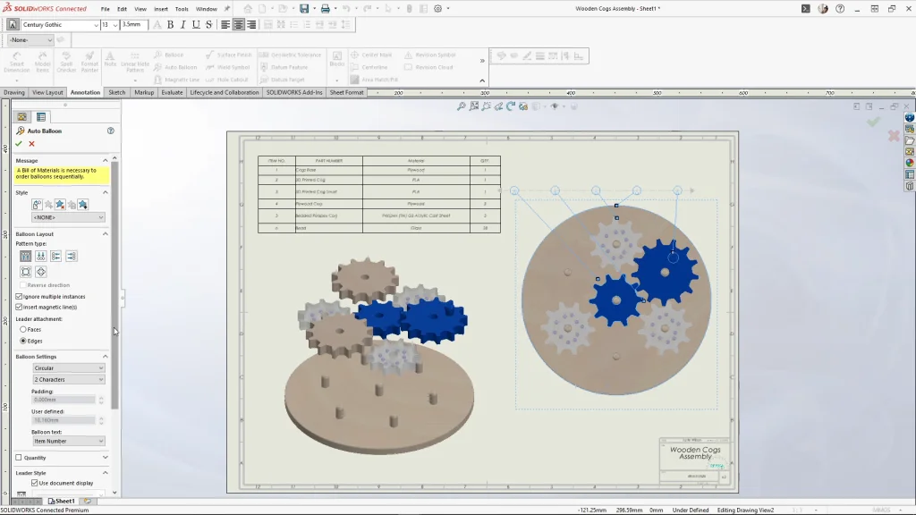
Next, I used the auto balloon feature to my top drawing view. Under the balloon layout, you can choose the pattern type, for mine I chose the balloons on top. With the balloons all above my view labeling one of each assembly part for the cogs toy, I could drag individual balloons along or drag the arrow along which pulls all of the balloons to line up with the drawing view side. If I don’t like the location of the arrows, you can simply drag the arrows along the edge of a part but be careful not to snap the arrow onto a different part as the balloon number will change.
I created a second sheet for the cogs base part to add in dimensions. I sent Jonathan the DXF files for laser cutting the Plywood and Perspex cogs, and the STL files for the 3D printed cogs. So, this drawing sheet will act only as a reference file for overall sizing, materials, and quantities, it doesn’t have to be very in depth.
To add a title or heading to a part, you can select the part you want to label and use the note tool, selecting the link to property icon I needed to change the ‘use custom properties from’ option to model found here. For the property name, I selected ‘file name’ from the drop down and applied it. Here I’ll get a title note, before I dropped the note I removed the arrow. Dropping the title above my drawing view I could change the font options using the font toolbar.
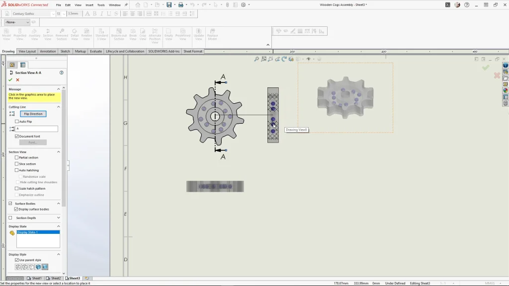
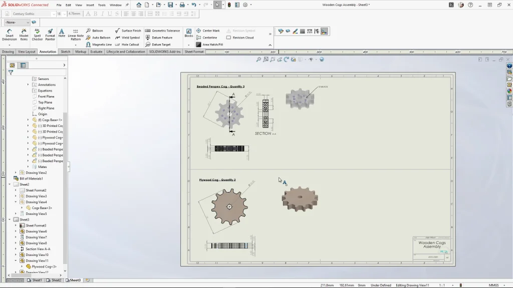
Moving onto sheet 3, I began adding in the cogs. Starting with the Perspex one, I used the same drawing views as the base part, an isometric, top and front view. However, the Perspex cog needed an extra view, using the drawing tab, I used the section view feature and the vertical cutting line to create a section view of the cog from the center of it. This was needed to show Jonathan there needs to be a hollow void within the cog to drop in the beads. This was important as the beads need enough room to move around inside the cog.
I’m then adding a title and some overall simple dimensions to my views. Again, these don’t need to be in depth as the DXF outlines of the cogs have been sent to Jonathan using the platform. I also added a note for Jonathan to add 10 beads to each Perspex cog. I used edit sheet format to extend a sketch line and divide up the page horizontally in half. This helps me keep my drawing views from another part separate, it’s useful when you have multiple smaller parts that you want to add to a single sheet without confusing the person viewing your drawing sheet.
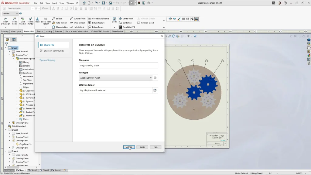
Skipping ahead, I added in the plywood cog, followed by the smaller 3D printed cog and the larger 3D printed cog that has a handle attached. Once I was happy with my sheet, I could save the drawing sheet and select ‘file’, and the ‘share’ option to share my file onto the 3D Drive on the 3D Experience platform as a Adobe 2d pdf. Then I could select upload and choose where I wanted my file to go. This would export my sheet to the platform. If I make any updates to my drawing sheet, I am able to update the shared file which is a very useful feature.
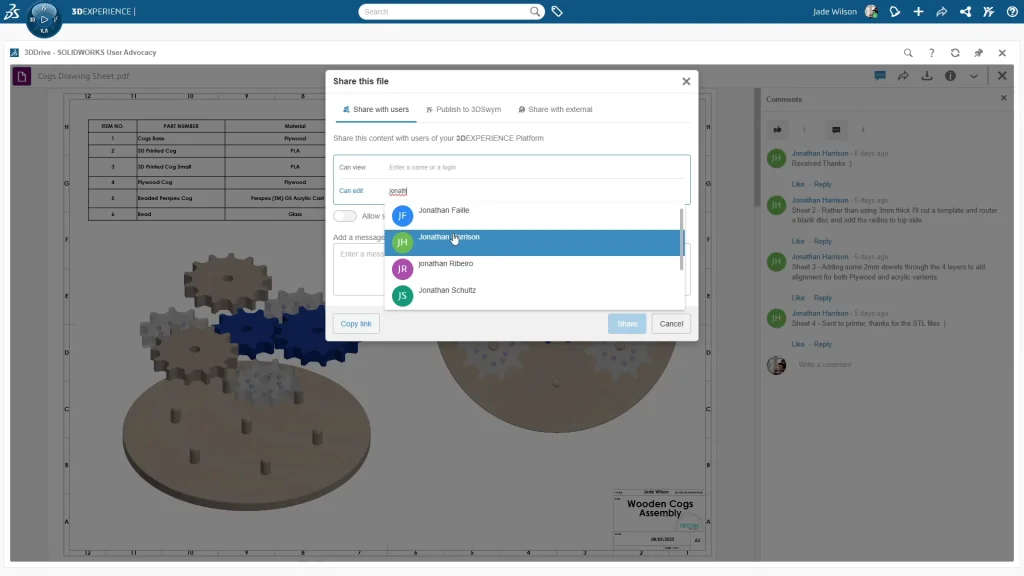
Moving onto the platform, I can open my drawing sheet from my 3D Drive. When I open the drawing, you’ll see that I had already shared my file with Jonathan, and he had made some comments. To share a file with someone on the platform, you can use the share icon. Under share with users, you can type in a name to share for people to view, or you can type into the ‘can edit’ box to allow people to edit your file. When I start typing, Jonathan’s name pops up and I could select it. I could also add a message. From here, I copied the link and selected ‘share’. I finished by sending Jonathan the file link via a message to help him find the file quickly.
I’m then able to reply to Jonathan’s notes and wait for him to update me on the progress of the project. Keep your eyes peeled for Part two of this tutorial where you will see Jonathan take on the challenge of producing a prototype of this cogs toy.