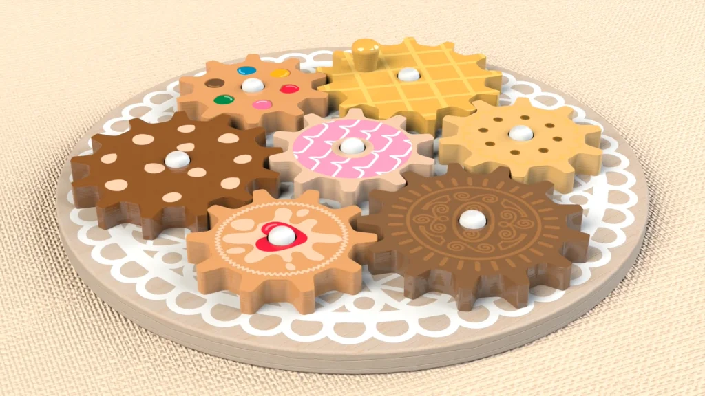

For this tasty biscuit themed tutorial, I wanted to play around with modeling custom cogs for a wooden toy design. If you are following this tutorial, you will need to download the files here

There are two different sized cogs needed for this toy, one has 10 teeth and the other has 13, I have already pre-calculated the size I need each cog to be for the overall size of my toy. In this tutorial I will demonstrate the use of circular pattern, save bodies and motion study with motors. All the cogs for the design were modeled within one part file, I could have created one copy of each sized cog, but by modeling all of them in the one part file I could test the overall placement of the cogs, but more importantly for this design, I have a different appearance and decal applied to each cog, so individual parts are needed for each cog biscuit type. If I were to only add a different appearance to each cog, configurations with linked display states could be used instead.
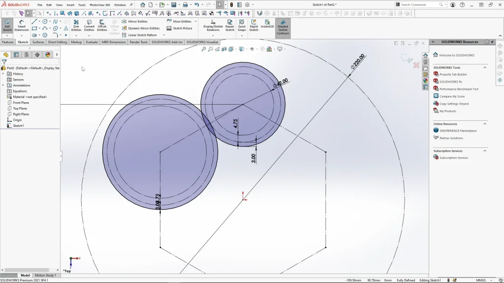
I began with a new part and sketched a guide circle which represents the overall size of my toy base part, and also a hexagon to help place the cogs into the right place at the same distances apart. I could then use the points of the hexagon to create the guides for my two cogs. There is an inner circle for the inner diameter of the cog, this is where the teeth would end. A middle circle for the cross/intersection point of the cog teeth and then the outer circle for the overall cog size. The ratio difference between my cogs is 1:1.36, this can change but the teeth ratio may not match up unless it is also 1:1.3 teeth.
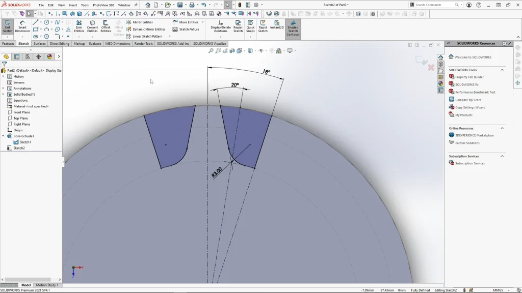
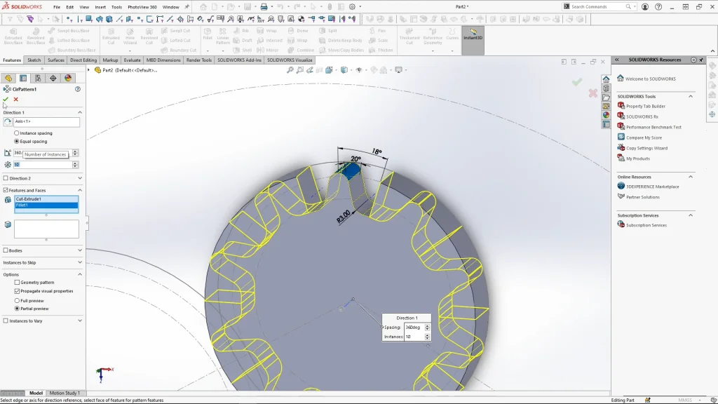
When creating the tooth sketch, I start by creating half of the tooth between 3 centerlines, The angle between the outer centerline guides of the tooth is calculated by dividing 360 degrees by the number of teeth of that cog, which is 10 for the smaller cog, this is then divided by 2 this will form half of the tooth. This gives me an angle of 18 degrees. The tooth sketch itself has a gear pressure angle of 20 degrees, any gear working with this gear would have to have the same pressure angle. The tooth sketch is then mirrored over and cut through the cog. I softened the overall tooth with fillets before it was patterned.
Circular pattern is then used to pattern the tooth around the cog with 10 instances. I repeated the same sketch process with the larger cog, only this time I needed to divide the cog for 13 teeth. When I applied the angle dimension, I input 360 divided by the number of teeth, 13, and divided by 2, this equals 13.85 degrees. A hole was added to each of the cog centers to allow them to slot onto the toys base. Once I had both cogs created, I moved / copied the smaller cog to the center of the hexagon and circular patterned the two cogs around this by 3 instances.
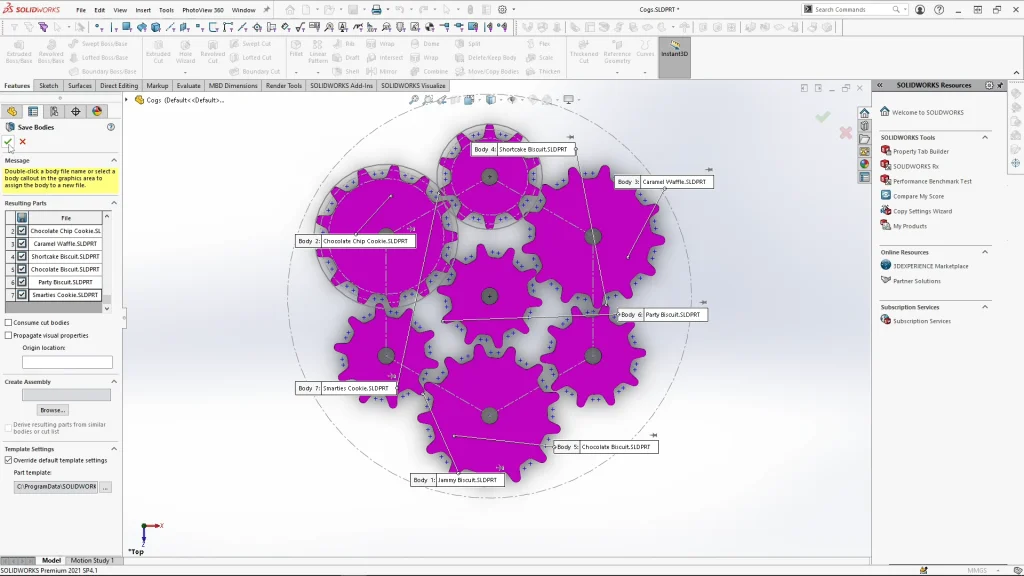
All of the cog solid bodies were all renamed to the corresponding biscuit design, that way when I opened them up as individual part files, I could apply appearances and my custom biscuit decals. I have added the finished cogs to the download file, I don’t demonstrate adding the decals or appearances in the tutorial, but you can play around with the deals from the file if you wish to, or you can use my cogs for the final assembly. In the assembly I do show you how to add a handle extrusion to the waffle style biscuit, this would be used for the play aspect of the toy, but it is also the cog I add the motor to in the motion study further on into the tutorial.
With all the cogs saved as parts, I could create the assembly of the toy. The base part was a fixed component in the assembly. I used concentric mates to place the cogs onto each peg of the base, ensuring lock rotation is unticked. I also applied a coincident mate to the underside face of the cog and the top face of the base. Before I could move onto the motion study, I needed to adjust the placement of the cogs, you can just do this by eye. There can be no overlapping before the motion study is created, otherwise it would likely error.
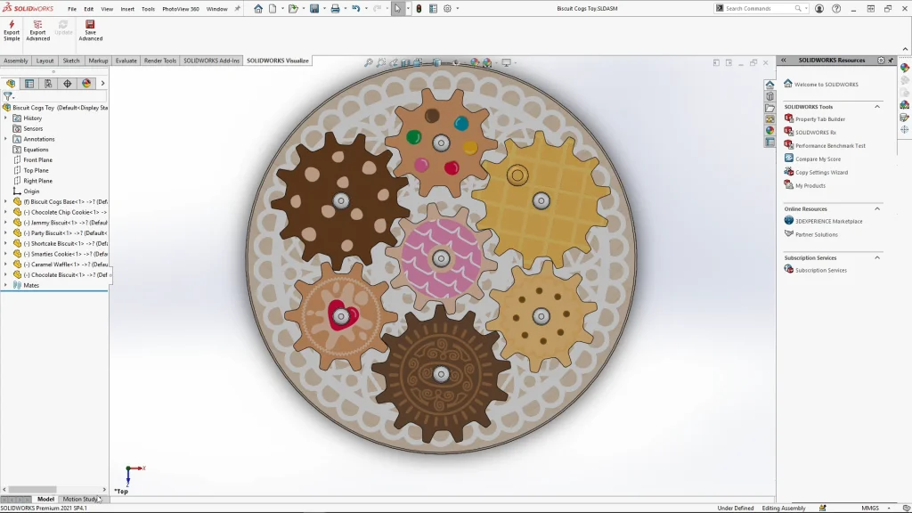
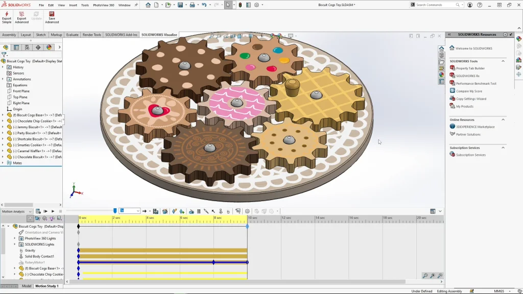
Finally, the fun part is the motion study, I changed the study type to motion analysis, and applied gravity along the y axis, I always add gravity even if I think my mates over define it. Next, I add contacts, selecting all components as they will all be interacting with each other. Then I applied a motor to the top face of the waffle cog moving clockwise. For the speed of the motor, 6rpm is plenty. Dragging the black diamond time key of the study to 10 seconds, and the time bar to 8 seconds, I could edit the motor at 8 seconds to lower the speed of the cog to 4rpm and apply it. Then dragging the time bar to 10 seconds, I could reselect and edit the motor again and turn it off to stop the motor completely at this point. Once I have calculated my analysis, I can export out my animation with the visualize tab and the export advanced options which allows me to send out the study information. Within SOLIDWORKS visualize I can create rendered animations, you can see the final animation I created at the end of the tutorial.