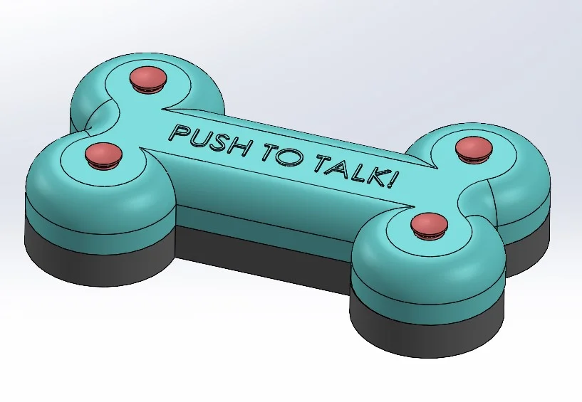

Okay, I’ll start by saying the title of this blog might be a little bit of a stretch of the story. However, what I’d be designing did have some potential to allow our dog to communicate with us in an easier way. For this project I intended to make a soundboard which was dog themed and would be capable of being activated by a push from a paw.

I’d made a soundboard in the past for some costume projects I’ve been involved such as the magic wheel chair myself and Kirby Downey built as part of The CORE Podcast, if you’re interested in that build you can check it out [here]
The first part of this project was to model up purchased components such as the PCB, battery pack and speaker modules along with the push buttons I’d be using. From here, I’d be able to create the housing or casing which I would 3D print to contain all the electronic components. As these components aren’t crucial to my design and we’re not doing electronic component design here I used “bluff” bodies to mock up the components within the assembly. A bluff body is basically the same overall external dimensions with the same mounting points as the full detailed component but much simpler to allow for faster creation of models.
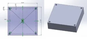
I started by modeling the PCB component, this was a simple rectangle 53mm by 51mm in size extruded 15mm in height. I then sketched the four mounting holes in the initial rectangle sketch meaning that when I extruded this body my holes were already present, no need to go back, resketch and then finally use the cut extrude commend. Two actions completed in one sketch and command!
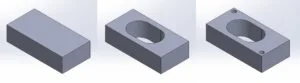
The speaker unit I used had an external size of 70 by 35 by 15mm, I started by creating a rectangle in a new sketch to match this size and extruding by the required height. I used the extrude cut command to create holes through the solid body where these would be required to mount. As the speaker unit had a certain portion which produced sound, I needed to create an area in the housing to allow the sound to escape through, to make this easier I created a new sketch of a circle in the same potion as the functional part of the speaker. I used the cut extrude command to remove this portion of the body which would make aligning this with any open area in the housing, I find that this a great method for aligning critical areas such as this much easier.
I also had a battery pack which I needed to fit into the housing which I had to design. Again, to make this easier I created a bluff body of this component to allow me to more easily create the designed housing. As with the PCB and speaker modules I created this in the same simple manner.
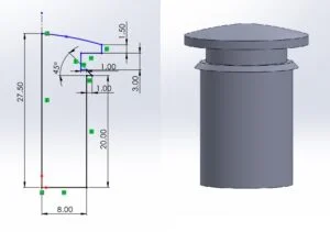
The final component I made was the metal mushroom momentary push buttons I had purchased to activate the soundboard with. I sketched out the cross section of the button as best as possible from the measurements I had taken using a vernier caliper, once I had this sketch completed, I used the revolve tool to create a new body revolved around a centerline within the sketch.
Now that I had all the components created, I started a new assembly into which I inserted the speaker module, PCB and battery pack. I arranged these into something like the configuration I thought I needed and took some very rough measurements from the arrangement, I noted these down onto some scrap paper I had laying around on my desk.
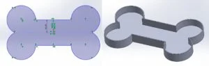
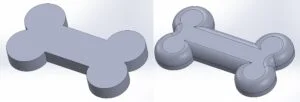
With my rough measurements in front of me it was time to get started with the design of the housing. To get started I created a new sketch in the top plane and sketched out the rough dimensions I had noted down as a starting point. From here I could get to work with the outline of the shape I wanted to create. As this was to be a soundboard for a dog, I wanted the outline of the housing to be bone shaped, as this design incorporated some symmetry lines, I would only need to sketch out ¼ of the design before mirroring to create the rest. I had setup the sketch to be about the origin center point and I got to work by sketching a vertical and horizontal construction line from this point, these would act as my lines of reference for the mirror command later in the process. I sketched out the required portion of the bone shape as large as required to encapsulate the components needed. From this point I added some dimensions to lock these lines into place before offsetting the sketch 2mm to create a second line slightly further out than the original sketch.
With the sketch completed, I used the extrude command to create a flat baseplate 2mm in thickness, I then selected the same sketch in the feature tree before again using the extrude command to create a thin wall the 2mm in thickness set earlier, this wall was set to a height of 20mm.
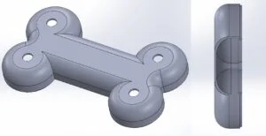
The next challenge for the base of the housing was to add small upstands into which I could use heat set inserts to create a thread, to secure the components into position. I started by creating a new sketch on the upper base surface, before adding 6mm circles at the points where the securing screws would need to mount into, before sketching another 4.1mm in diameter within these. I then extruded these 5mm in distance to create small upstands into which I would insert heat set threaded inserts to provide a nice metal thread to secure against.
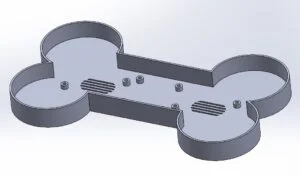
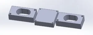
I needed to add small through holes in the base which I could use to secure the lid section using small screws. I started by creating a new sketch on the base surface, I then added 4x 10mm circles in suitable positions around the design. I extruded these 3mm upwards. My next move was to cut a hole in the center of each of these raise area through all with a diameter of 3mm. From here I added a blind cut on the underside 2mm in depth with a diameter of 6mm, this cutout would provide a recess for the screw heads to sit within. The final piece of this puzzle was to add 6x recesses on the base of the part to allow some small rubber feet to sit within, the feet I had were 10mm in diameter, so I made each cutout 10.5mm in diameter to allow for printing tolerances. These were cut 0.2mm in depth to allow them to securely fit into the newly created recess.
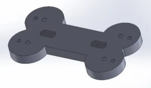
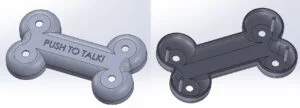
With the base piece done it was time to focus my energy on the upper lid section, I did a bit of a cheat code and copied the original sketch I had made for the base piece into a new part and pasted this onto the top plane. From here I extruded this 30mm before then using the inner line on this same sketch to cut a pocket upwards into this 27mm. To create more of a bone shape for the upper segment I added two 15mm radius fillets to the inner and outer edges which resulted in the below design!
Now I had the shape outlines, I needed to add four 20mm diameter cutouts to allow the push buttons to pass through and connect to the PCD. I started a new sketch on the created flat upper surface and drew a 20mm circle in the center. From here I used a linear pattern to create another one, equally spaced either side of the original. A simple cut extrude through all made quick work of creating the needed cutouts. With assembly in mind, I needed to add a step to aid alignment. To achieve this, I made a new sketch on the bottom surface of the lid, offset the inner edge by 2mm and extruded in both directions 5mm, by doing this in both directions I created a joined body which could sit inside of the edge of the base piece.
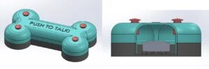
I now needed a way to hold both parts together… during my modeling of the base component I had created 6 small through holes with a counter bore to allow me to use M4 screws to pull the lid into the base which would hold it securely in place. All I needed to do was replicate the positions of these on the lid and create a connection stalk which could be screwed in. I added another sketch on the top plane and drew construction geometry to allow me to create the stalks in the same positions as the holes in the base. Again, I cheated with this sketch and copied it across from the base component using the move command to align it correctly. Once I had this aligned, I extruded up to surface, selecting the inner surface of the lid and down the 20mm required to meet the bases lower surface. With these 4 stalks in place, I added a 4.1mm cutout 6mm deep in each to allow me again to insert some M3 heat set inserts into these.
Now I had all the components created I quickly placed these into a new assembly to check all the fitments were correct, which made me think about my lid and base fitting together. I went back and made a change to the interface where they would align and added a 0.2mm gap in this area to allow these to fit correctly once printed. The rest of the model came together nicely, and it was soon time to get to work making my design come to life.
Check back soon for part two, where I show you how I made this design come to life, for now you can check out the designing.