

Hello to all,
Welcome to the new edition of the SOLIDWORKS® Support Monthly News! This monthly news blog is co-authored by members of the SOLIDWORKS® Technical Support teams worldwide. Here is the list of topics covered in this month’s Blog:
- SOLIDWORKS® Toolbox Data Utilities: Essential Tools for Maintaining Your Toolbox
- Why do STL file sizes explode compared to native SOLIDWORKS files?
- Flex Feature in SOLIDWORKS®
1. SOLIDWORKS® Toolbox Data Utilities: Essential Tools for Maintaining Your Toolbox
– Deepika PUJARI
SOLIDWORKS Toolbox is a powerful library of standard hardware components, but over time — especially with upgrades, migrations, or environment changes — the Toolbox database can become misconfigured or outdated. That is where Toolbox Data Utilities come in.
This blog covers three key tools provided by SOLIDWORKS for managing and repairing your Toolbox:
- DatabaseConverter.exe
- sldsetdocprop.exe
- UpdateBrowserDatabase.exe
Each of these utilities is located in your SOLIDWORKS installation directory and serves a specific purpose to ensure your Toolbox is functioning correctly.
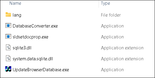
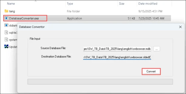
1. DatebaseConverter.exe
Converts the Toolbox database from the legacy .mdb format (Microsoft Access) to the newer .sldedb format introduced in recent versions of SOLIDWORKS. The .sldedb format is more secure, scalable, and robust.
⚠️Use this tool only when upgrading Toolbox database formats.
When to Use:
- You are upgrading from an older SOLIDWORKS version (2015 or earlier).
- You still have a swbrowser.mdb file in your Toolbox directory.
- You want to transition to the .sldedb format.
Steps to Use:
- Backup your entire Toolbox folder (critical).
- Navigate to: “C:Program FilesSOLIDWORKS CorpSOLIDWORKSToolboxdata utilities”
- Run DatabaseConverter.exe as Administrator.
- Browse and select your swbrowser.mdb file.
- Choose the destination for the new .sldedb file (typically same folder).
- Click Convert.
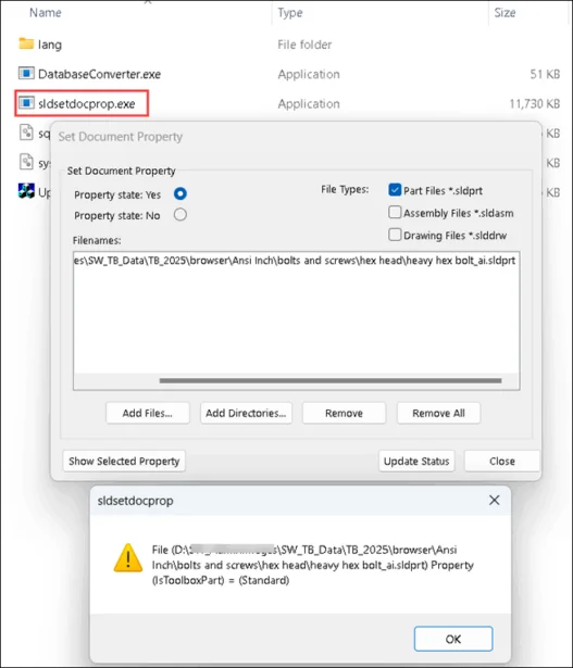
2. sldsetdocprop.exe
Fixes or sets the Toolbox property flag on SOLIDWORKS parts. This is essential when:
- Custom parts lose Toolbox association.
- Toolbox parts are incorrectly flagged, preventing proper reuse.
- You are cleaning up parts moved outside the Toolbox.
When to Use:
- You copied Toolbox parts outside the Toolbox directory.
- You are preparing parts for PDM and need the correct document properties.
- You are seeing errors when inserting hardware or creating Smart Fasteners.
Steps to Use:
- Navigate to: “C:Program FilesSOLIDWORKS CorpSOLIDWORKSToolboxdata utilities”
- Run sldsetdocprop.exe as Administrator.
- Choose the folder containing affected part files.
- Select the operation:
- Set as Toolbox part
- Clear Toolbox flag
- Check Toolbox property
- Click Apply.
⚠️Always review part usage before clearing the Toolbox flag — you may unintentionally break references in assemblies.
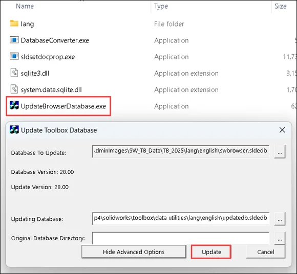
3. UpdateBrowserDatabase.exe
(Also known as Toolbox Settings Tool / Browser Database Updater)
Scans and updates the Toolbox database for compatibility, integrity, and version mismatches. It is often used during upgrades to newer SOLIDWORKS versions.
When to Use:
- You have installed a new SOLIDWORKS version and want to upgrade Toolbox.
- Toolbox components do not show up or behave unexpectedly.
- Toolbox Settings (swbrowser.sldedb) throws errors or seems outdated.
- You are repairing a corrupt Toolbox configuration.
Steps to Use:
- Launch UpdateBrowserDatabase.exe from: “C:Program FilesSOLIDWORKS CorpSOLIDWORKSToolboxdata utilities”
- Select your Toolbox folder (typically “C:SOLIDWORKS Data”).
- Click Next to begin the scan.
- Review results — the tool will prompt for repair or upgrade if needed.
- Click Update/Repair and wait for it to complete.
⚠️You must have Administrator access and full read/write permissions to the Toolbox database files:
- .sldedb
- .index
- .dat
Admin & Permissions Reminders
For all utilities:
- Run these tools as Administrator.
- Ensure no one else is accessing the Toolbox during the repair/update.
- Always maintain a complete backup before changes.
⚠️If you are maintaining Toolbox across multiple environments (local, PDM, network), always test changes in a sandbox setup before deploying to production.
2. Why do STL file sizes explode compared to native SOLIDWORKS files?
– Tushar NAYAK
If you’ve ever exported a SOLIDWORKS part or assembly to STL, you may have noticed something strange:
A smaller sized .SLDPRT file (a few MBs) can suddenly become a massive .STL file (hundreds of MBs). At first glance, it feels like SOLIDWORKS is duplicating data OR saving inefficiently. But the real reason is rooted in how STL files work.
Below listed are the difference between saving file as native SOLIDWORKS file format and as STLs.
1. How the geometry is stored?
- SOLIDWORKS Files (.SLDPRT, .SLDASM)
- Store geometry as parametric, analytic data.
- It is highly efficient as the same cylinder can be described in a few parameters, regardless of its size.
- STL Files
- Store geometry as tessellated meshes of triangles.
- That same cylinder is approximated by thousands of tiny flat facets.
- More facets give smoother curve, but also a much larger file.
This shift from math-driven geometry to triangle soup is the core reason for file size explosions.
2. What makes STL files grow so large?
- Resolution Settings
- When exporting to STL, SOLIDWORKS asks for Deviation and Angle Tolerance.
- Smaller values give more triangles hence smoother surface which leads to bigger file size.
- Curved Surfaces
- Planar faces tessellate into just 2 triangles.
- Cylinders, spheres, splines, or fillets may need thousands of triangles.
- Assemblies with Many Components
- Each part contributes its own mesh.
- Even small fillets or holes add up across large assemblies.
- Unit Scale
- Exporting in millimeters instead of inches can create finer meshes (depending on settings).
3. How to control STL file size?
- Adjust Export Settings
- Go to File > Save as.. > STL > Options > Increase Deviation or Angle values slightly.
- Balance quality vs. size
- Use Binary Format
- STL supports ASCII or Binary.
- Prefer Binary STL as it is typically 5 – 6 times smaller in size.
- Simplify Geometry
- Suppress tiny fillets, cosmetic threads, or small features if not needed for printing/manufacturing.
- Use Defeature tool for assemblies
- Tools > Defeature can strip internal details before export, cutting STL size drastically.
If your STL is too large to share or slice, you can also consider exporting to 3MF instead. It is smaller in size, retains colors/materials, supported by most modern slicers and 3D printers.
The hike in size from SOLIDWORKS to STL isn’t inefficiency it’s rather the cost of converting smooth mathematical surfaces into triangles. With the right settings, you can keep file sizes reasonable without losing print quality. Next time, if your STL increases in size, remember to tweak the tessellation, go Binary, and simplify geometry. Your hard Drive will thank you for that!
3. Flex Feature in SOLIDWORKS®
– Kundlik GADADE
The Flex Feature in SOLIDWORKS® enables users to deform solid or surface bodies in an intuitive and predictable manner. It provides four deformation types: Bending, Twisting, Tapering, and Stretching. By applying Flex, designers can create complex shapes and explore design alternatives without rebuilding geometry from scratch.
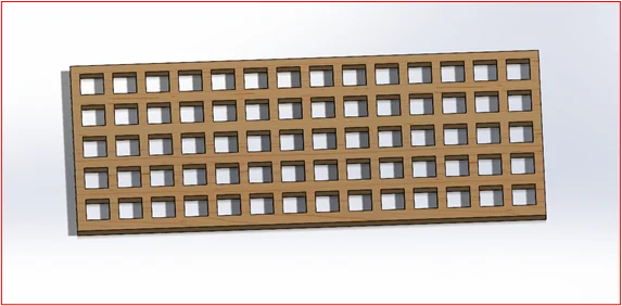
In the following example, a rectangular panel with multiple square cutouts is used as the base model. This model is representative of an architectural facade or sculptural form where Flex operations can simulate real world deformations.
Base Model: Rectangular Panel with Cutouts
The initial geometry is a rectangular solid body with uniformly spaced square cutouts, resembling a facade or decorative panel.
Applying the Flex Feature
In this example, two sequential Flex operations are applied:
Twisting: to rotate the panel geometry along an axis.
Bending: to add curvature on top of the twisted geometry.
This demonstrates how Flex Features can be combined to create complex and visually realistic transformations.
Step 1: Accessing the Flex Feature
- Navigate to Insert > Features > Flex. In the PropertyManager, a triad and bounding box will appear around the body.
- The bounding box defines the extent of the deformation.
- Trim planes indicate the start and end of the deformation region.
- The triad defines the center and direction of deformation and can be re-positioned.
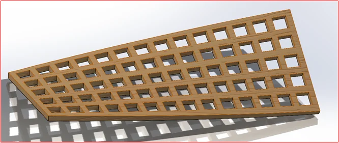
Step 2: Applying a Twist Flex
- In the Flex PropertyManager, select Twisting as the Flex type.
- Define the angle of twist (e.g., 20°–30°) depending on the required deformation.
- Adjust the trim planes if needed to restrict twisting to a specific portion of the panel.
- Click OK to apply the Twist Flex.
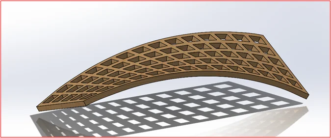
Step 3: Adding a Bend Flex on Top of Twist
- With the twisted panel geometry, re-activate the Flex Feature.
- Select Bending as the Flex type.
- Specify the bending angle and radius to achieve the desired curvature.
- Reposition the triad to control the bending direction.
- Click OK to apply.
The Twist Flex rotated the panel, creating a spiral-like appearance while preserving the cutouts.
The Bend Flex added curvature to the already twisted geometry, demonstrating that Flex Features can be stacked sequentially.
The final result is a panel that combines twisting and bending, resembling architectural facade elements or sculptural forms.
Applications of the Flex Feature
- Mechanical Design: Simulating twisted shafts, bent pipes, or tapered components.
- Industrial Design: Exploring conceptual forms for bottles, consumer products, or enclosures.
- Architecture: Designing panels, facades, or shading devices with complex curvature.
- Tooling: Adjusting molds, dies, and stamping components.
Summary: The Flex Feature in SOLIDWORKS® offers a powerful way to deform geometry using Bending, Twisting, Tapering, and Stretching. In this example, applying Twist followed by Bend illustrated how multiple Flex operations can be combined to generate realistic and intricate transformations for practical design scenarios.