
Modeling a spring can be a relatively basic exercise in SOLIDWORKS for those who have some experience under their belt. It’s one of the earlier segments in the Advanced Part Modeling course offered by many SOLIDWORKS resellers, and as long as you know what a Sweep is, and you know how to create a Helix, you’re pretty much set (and if you don’t, consider taking the course above).
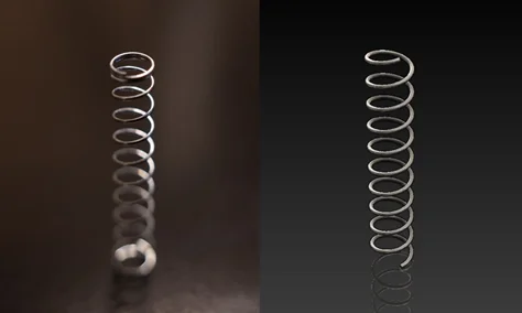
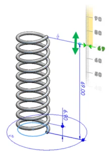
A photo of a small compression spring versus its 2-minute equivalent in SOLIDWORKS.
Now, there are plenty of ways to make a spring more complex. You can add a taper to the helix, you can create smaller and larger sections, add hooks to the ends to create a tension spring, use Cut with Surface to create Ground Ends. The list is nearly endless, and Jeff Setzer wrote an article over a decade ago that covers almost every trick in the book for designing springs. All these best practices still apply today, so I encourage you to go check that article out.
Far and away, though, the question I’m asked most often is, “how do I make my spring show motion?” or some variation thereof. And the truth is, this question is incredibly simple and very complex at the same time. So in this article, let’s examine why that’s the case, and explain how you can design your springs with movement using both a simple and a more complex approach.
Simple Approach: Use Instant3D with a Plain Old Helical Spring
Believe it or not, even the most basic springs have dynamic movement built in (technically). Specifically, the Instant3D functionality can be used to modify and update the length of the spring in real time, so you can see the spacing between coils increase and decrease as you make adjustments.
To create a basic spring, sketch and fully define a circle on a plane of your choice, confirm the sketch, and then create a helix using the Curves dropdown in the Features tab of the CommandManager. Select the sketched circle as the reference for the helix, and then adjust the helix parameters as required.
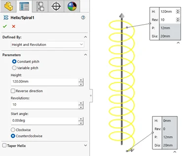
Creating a basic helix.
For less experienced users, it’s recommended to use one of the “Defined By” options that includes the Height parameter. This will make the process of adjusting the spring length more intuitive.
Once complete, this helix can then be used as the path for a Swept Boss feature, using the option for Circular Profile and providing a diameter to keep things simple.
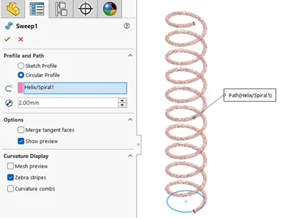
Creating a spring by sweeping a circular profile along the helical curve.
Once the spring has been created, you’ll need to find the dimension that controls the spring length (this will be an obvious length dimension unless the “Pitch and Revolution” or “Spiral” option was used to define the helix in the previous step). Locate the Helix feature in the FeatureManager Design Tree and click it a single time (do not double click). The dimensions of the helix should appear on the screen like so:
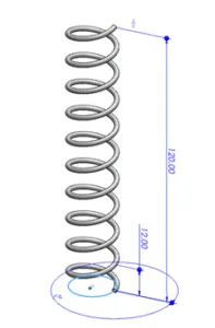
A simple spring with dimensions displayed.
If the dimensions do not appear after a single click, or the dark blue circular handles do not appear at the ends of the dimensions as pictured above, Instant3D is likely disabled. In this case, navigate to the Features tab to find Instant3D and enable it.
Once Instant3D is enabled, click and drag the dark blue circular handle attached to the end of the spring length dimension. The length will automatically be updated, and the spring will stretch or compress in real time according to the new value.
Adjusting spring length in real time using Instant3D.
For some relatively simple applications, this approach may be just enough to get the job done. But for most people asking how to show motion in springs, they’re looking for a little more capability than this.
This approach has several limitations, but most notably:
- It cannot be used dynamically in animations or Motion Studies.
- It will not automatically adjust when used in assemblies.
- Changing it requires you to modify a dimension of the helical curve, which is a parent feature of the Sweep that generates the geometry (this can get messy).
So, assuming your needs are beyond this use case, where do we go from here? The Advanced approach solves each of these limitations, but requires quite a bit more work.
Advanced Approach: Create a Spring without a Helix or a Length Dimension
So, why can’t the Simple approach be used to represent dynamic motion? The big limitation is that to change the length of the spring, we have to change a dimension value that is buried within a sequence of operations. If you followed the Simple approach, your design tree would look something like this.
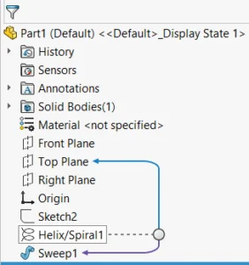
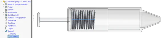
The Feature Tree of a simple spring design.
The Sweep feature creates the geometry of the spring, but uses the Helix feature as the path, which in turn contains the dimension we have to modify to change the spring length. Generally speaking, SOLIDWORKS does not like to propagate design changes through multiple levels of feature dependency, and rebuilds do not happen automatically after changing sketch dimension values for performance reasons.
In addition to all this, I’d like to remind you that a dimension value is just another constraint, and in the context of an assembly, there are very few instances where the length of a spring should be driving the position of the surrounding components. Rather, the position of the assembly components should be driving the length of the spring. So what do we do?
Get rid of the helix and the length dimension!
Most of this problem could hypothetically be solved if we were able to suppress or delete the length/height dimension associated with the helix, but since a helix is a feature, and the length dimension is required by the feature, there’s no way around this. So get out your thinking caps, it’s time for a workaround!
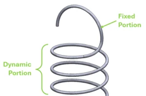
The helical nature of our spring can be replicated without a helix by using a Swept Boss constructed from an undimensioned vertical line path and a circular profile constructed offset from the path as shown (these should be created as separate sketches, or the sweep feature may fail due to the options required).
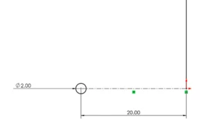
A straight line of arbitrary length representing the spring path and a circle representing the spring profile. The 20mm dimension shown here represents the radius of the coils.
With this sketch created, start a Swept Boss feature, selecting the circle as the profile and the line as the path. You will likely notice no preview initially, indicating that the feature will fail.
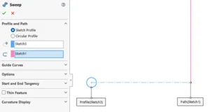
No Sweep preview, indicating that the feature will fail with the given parameters.
This is because with the current selections, the circle would be swept along the same plane it’s sketched on, failing to sweep through any volume. However, the Options dropdown allows us to specify a twist value manually.
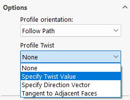
Profile Twist options available for the Swept Boss feature.
Specifying a twist value greater than zero degrees will cause the profile to rotate around the straight-line path by the amount specified over the length of the sweep while respecting the sketched offset distance (20mm in this case). Consider changing the Twist control parameter to revolutions to more easily define the number of coils created.
Preview of the spring at ten revolutions of specified twist.
Confirm the sweep feature to generate the geometry. Now that the spring is free of a length dimension and doesn’t rely on a helix, the possibilities are endless! Simply dragging the line segment in the sketch controlling the length of the spring will automatically rebuild it accordingly. This may seem very similar to the Simple approach, but importantly, this method is compatible with assemblies with just a bit more work.
You will likely want to create a reference Axis from the intersection of planes along the spring’s length and other reference features. These can simplify mating in assemblies.
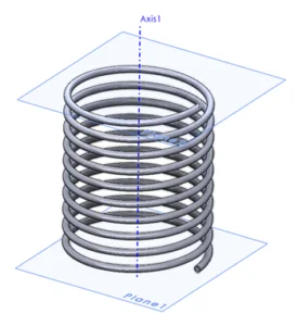
An undimensioned spring shown with reference planes and an axis for mating.
It’s important to note that simply adding this spring to an assembly and mating it to existing components will not show the dynamic motion you’re likely looking for. By default, components added to an assembly behave as rigid bodies, even if they have parameters at the part level that are underdefined. Here, I’ve modeled a simple syringe to illustrate this effect.
A fully-defined syringe assembly with no motion available.
In fact, in this particular case, the size of the spring is pulling the plunger component into an impossible position. To correct this behavior, our final step will be to replace one of the spring’s mates with an in-context relation to make the length of the spring dependent on the position of the components.
First, I’ll remove the Coincident mate between the plane at the end of the spring, allowing free movement of both the spring and the plunger. Then, right-click the spring component and use the Edit Part command to begin editing the part in the context of the assembly.
Syringe assembly shown with the Edit Part icon, found in the right-click context menu.
Depending on your system settings, the spring may turn blue, or the rest of the assembly may become transparent, or some combination thereof — but you should now be in Edit Part mode. From here, we can edit the sketch controlling the spring length and attach it to another component within the assembly, creating the in-context relation that will allow the spring length to update dynamically as we move the plunger.
Syringe assembly in Edit Part mode with the sketch controlling spring length selected.
Depending on your design scenario, the relations required at this step will vary, but in most cases, the endpoint of the line segment controlling the spring length should be attached to a face, edge or vertex of another component using a Coincident relation, like so:
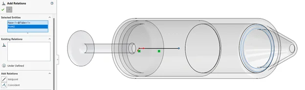
Line segment endpoint being attached to the end of the syringe tube via sketch relation.
As a reminder, this is a Coincident sketch relation, not an assembly mate, as we are editing a part in the context of an assembly. Once complete, simply confirm the sketch, then exit Edit Part mode, and you can officially test the dynamic behavior of your spring.
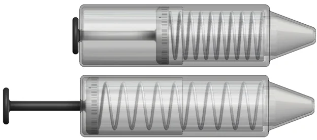
The spring before and after moving the plunger.
Updating the spring length will still require a rebuild after repositioning components (for now), but the surrounding components should now completely control the length of the spring. This unlocks a new level of design flexibility, along with animations and motion studies which can be saved directly as video files.
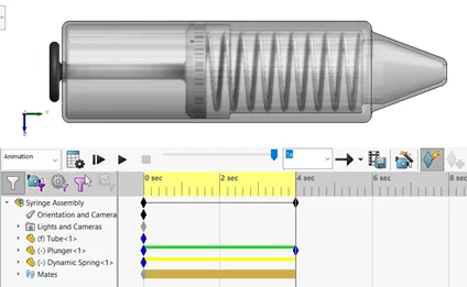
Animating the spring with a Motion Study.
Additional Thoughts
Now that you’ve mastered the concept of creating a dynamic spring, there are many ways to improve the realism and functionality of the spring. To wrap up, I’ll cover a few additional points to get your gears turning on what do next.
What if length really does matter?
This article assumes that the length of the spring is arbitrary, but that really depends on your specific circumstances. If preferred (or necessary), you can begin this design process with a dimension attached to the line segment representing the free length of the spring (or whatever length you prefer) to provide an initial state, but the dimensions must be removed in order to allow for dynamic motion.
To control the length of the spring more effectively, consider applying a Distance mate between the components that are attached by the spring. This mate comes with a dimension can be adjusted dynamically, similar to the sketch dimension used in the Simple approach. It also results in “true” dynamic behavior in that rebuilds are not required between adjustments and can be used with the Mate Controller feature.
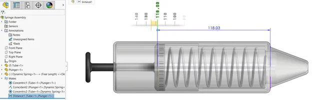
Adjusting spring length dynamically in an assembly using a Distance Mate.
Additionally, a Distance mate can be toggled to Driving or Driven as needed, allowing you to decide whether you want to set the spring length and have the component positions respond accordingly (driving) or vice versa (driven).
You can improve the realism of your designs further by using a LimitDistance mate instead to ensure that the components controlling the spring length only operate within a realistic range of values.
Subassemblies will make it seem like your dynamic springs aren’t working.
For performance reasons, subassemblies are set by default to behave as a rigid group of components. If you’d like to see dynamic spring movement at the subassembly level, the subassembly will need to be designated as flexible by right-clicking on it in the Design Tree and using the Make Subassembly Flexible command from the context menu. The icon looks like this:

The Make Subassembly Flexible icon.
This will allow your spring(s) to behave dynamically even at the subassembly level, but it should be noted that this may result in a performance hit depending on your system specs and quantity of flexible subassemblies.
Multiple contexts can be problematic.
Once you add the spring model to an assembly and add in-context relations to control its length, you are effectively creating a dependency between the spring and that specific assembly. If you intend to reuse the same spring model across multiple assemblies, this can become very messy, very quickly, and cause all sorts of things to break if you don’t prepare for it ahead of time.
Essentially, the spring model will always look back to the first assembly where the in-context relationship was created, and it will use that information to determine the spring length. This creates the possibility of conflicting model contexts, and while there are established best practices for handling this, such as making components flexible, they exceed the scope of this article (this is not the same as making subassemblies flexible as noted above).
You can learn more in the Top-Down Assembly Modeling section of the Assembly Modeling course offered by many SOLIDWORKS resellers.
Final Thoughts
From here, your spring models can be customized to be more realistic or more suited to your design needs as you see fit. You may wish to use Cut with Surface features to represent Ground Ends, add loops to represent a tension spring, create extra coils at reduced pitch, or any number of other features. So long as the spring portion of the design maintains its in-context relations, it will continue to stretch and compress as your designs change around it.
Simple sweep and loft features used to create a fixed hook feature while maintaining dynamic spring motion.
The in-context design strategy used throughout this article is very flexible and applies to much more than just spring designs, but there’s a lot to keep track of when using it. If you’re unfamiliar, consider doing some research or taking a training course to ensure you’re following all the best practices.
Did I miss something important about spring design? Come yell at me on LinkedIn and see what else I’ve been making! Until next time, thanks for reading and happy modeling!