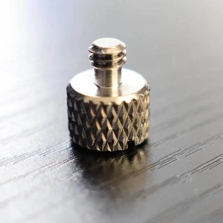

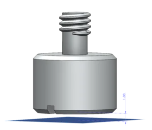
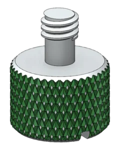
Knurling is a common manufacturing feature used to improve the grip on tools, fasteners and other everyday objects that are intended to be used by hand. This recognizable crisscross pattern can be found on weight training barbells, manufacturing tools, and even this simple thumb nut in the back of one of my monitors.

Knurling is everywhere, and while the geometry itself is rather simple — a repeating crisscross shape isn’t particularly “complex” — simple does not necessarily mean easy. This is true both in terms of the sketches and features used to create the knurling pattern as well as the computing power required to process and render it. The remarkable number of graphical triangles resulting from even the smallest of knurling patterns can prompt a graphics card meltdown and the appearance of everyone’s favorite dialog, if the proper precautions are not taken.
This article will cover the techniques required to create knurling features on both flat and cylindrical surfaces, and provide some valuable tips for reducing the performance impact that typically results from it.
Knurling on Flat Surfaces
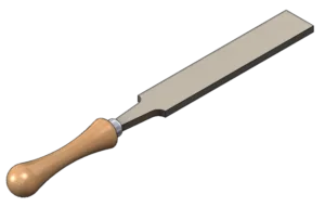
Knurling on flat surfaces is the most approachable, as simple straight lines, sketched profiles and extruded cuts are (almost) the only things required. We’ll use this simple flat rasp model as an example.
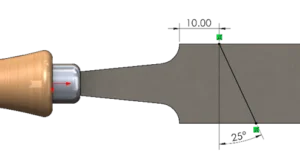
Begin by creating a straight-line path on the face where you’d like to create the knurling feature. The dimensions used should reflect the position where you’d like the knurling to start and equally importantly, the angle at which the knurling directions will intersect.
Then, create a plane perpendicular to the line. The simplest approach is to create a plane by using the line segment as the first reference, and one of the endpoints as the second reference.
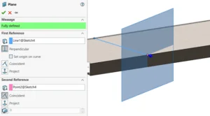
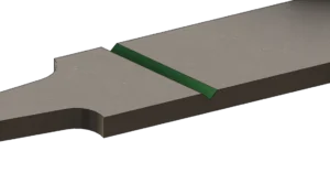
Next, create a new sketch on this plane and create the cross-sectional geometry of the knurling. This shape can vary depending on the type of knurling chosen, but is typically a triangle. Ensure that the peak of the triangle faces into the model if you plan to use cut features to produce the knurling pattern (as explained in this tutorial).
It’s most practical to create the profile with a collinear relation to the edge of the surface to be knurled, and then attach it to the previously sketched line segment via the midpoint using a pierce relation. This is not technically required for this use case, but is considered best practice when creating knurling in more advanced scenarios.
If you happen to find the Pierce relation too difficult, don’t worry. It’s not required for this technique (but it will be if you need to create knurling on cylinders, so get some practice in). The sketched line from the previous step is still important to set the orientation of the created sketch plane properly.
Next, use an Extruded Cut feature to remove material with the Through All – Both end condition active. If preferred, this strategy can be used with an inverted profile and an Extruded Boss feature to create knurling additively. When this is the case, Up To Surface end conditions should be specified in two directions. This will ensure that material on both sides of the profile is properly removed. At this point, you can hide the plane and any sketches for better visibility.
Now that all the hard work is done, and it’s time to take advantage of pattern features. Using a Linear Pattern, repeat this feature as many times as needed to complete the first direction of knurling, specifying the spacing and instances as required.
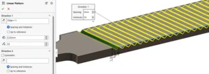
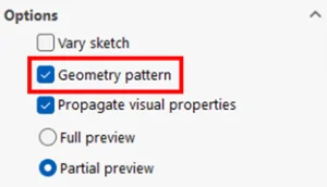
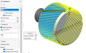
Additionally, enable the Geometry Pattern option in the pattern PropertyManager to improve processing speed whenever possible.
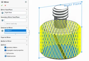
Once completed, this pattern can be copied across the plane of symmetry (right plane) to create the finished knurling feature. Again, the Geometry Pattern feature should be used for maximum performance.
Note that some of the knurling may need to be “filled in” to account for where the feature starts – this can typically be accomplished using a standard Boss Extrude feature. The completed knurling will have peaks and points according to the original sketched profile and spacing used between pattern instances.
Knurling on Cylindrical Surfaces
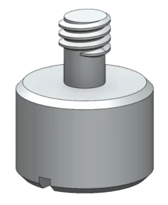
For cylindrical surfaces, the approach is similar but with some important differences — namely, the required use of a Helix to create the crisscross effect. For this example, we’ll use the thumb screw from my monitor, modeled up in SOLIDWORKS.
First, we’ll create an offset plane from the bottom surface of the cylinder. The distance here will vary depending on the size of your design, but this step is necessary to prevent excess material from being “missed” when we run a swept cut at a later step (this isn’t required for knurling on flat surfaces because “Through All – Both” is available as an end condition).
Next, create a circular sketch of the same diameter as the cylinder by converting the outer edge (or creating a coradial circle from scratch) within a new sketch on the plane created in the previous step. This circle can then be used as the basis for a Helix, which can be found in the Features tab of the CommandManager under Curves.
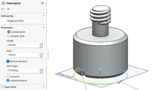
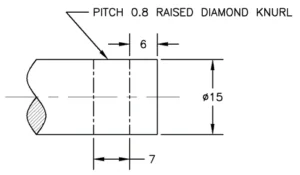
The Helix can be defined however you see fit, but as with the geometry for flat surfaces, it should reflect the angle that the knurling patterns will cross one another. In this case, I’ve chosen a steep pitch and only a partial revolution to match the real-world geometry of this fastener more closely. Importantly, the helix should extend beyond the bounds of the geometry to be knurled to avoid any missed or leftover material missed by the cut.
This helical curve will ensure that the profile created in the next step remains flush with the surface of the cylinder.
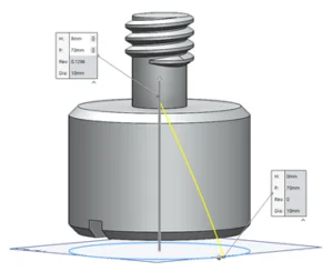
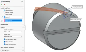
The cutting profile will be created next, using the same strategy as for flat surfaces. Create a plane perpendicular to the helix and positioned at its endpoint by using both the helix and its endpoint as plane references.
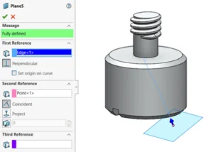
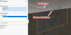
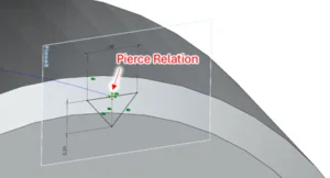
Once this plane has been created, start a new sketch on it and create the cross-sectional profile of the knurling in the same fashion as you would for flat surfaces. However, this time the Pierce relation is critical, as it will ensure that the profile remains connected to the helical profile throughout the sweep.
Consider using construction geometry and Symmetric relations as needed. Perpendicular and Tangent relations will also likely be required. In most cases, the midpoint of the line sketched tangent to the outer diameter of the cylinder should be connected to the helical path using a Pierce relation.
If you are struggling here, remember that a Pierce relation is always created between one point (from the profile) and one line or curve (from the path). A Pierce relation cannot be created between two points, so be sure to check your selections.
Now, create a Swept Cut feature using the created profile and path as the selections. Depending on the total curvature of the Helix you defined and the relations used to define the profile (parallel and perpendicular are preferred over horizontal and vertical) you may have issues with twist, in which case guide curves, direction vectors or other alternatives may be required. However, in most cases, simply setting the Profile Orientation option to Follow Path and the Profile Twist option to Minimum Twist should be sufficient.
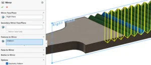
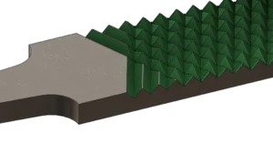
Once this seed cut is complete, it’s once again time to use a combination of patterning and mirroring to do the heavy lifting. This time the pattern is circular, but the Geometry Pattern option still applies (whenever possible). Use the cylindrical surface to define the axis of rotation for the pattern, and then define the spacing and number of instances as required.
Again, use a Mirror feature to create the crisscross effect.
The final pattern should emerge as you begin to hear your 5-year-old laptop fan do its best impression of a jet engine.
Now that you’re comfortable creating knurling, here’s a few tips on how to prevent it from slowing your design work down to a crawl.
Performance Considerations for Knurling
Even the most beautiful knurling pattern is worthless if it results in the entire model becoming useless. Due to the repetitive calculations and excessive graphical triangles, PC performance can take a substantial hit when rebuilding or even viewing knurling from the wrong angle, especially on aging hardware. The tips in this section should help to minimize this impact on performance.
Tip #1: Do you actually need knurling?
To be more specific, do you need to design knurling into your model? In most cases. when traditional manufacturing methods such as machining or forming are in play, a simple note indicating the type/shape of knurl, the pitch, the diameter (before and after the knurling is applied) and where the knurling should start and stop is all that’s required for a manufacturer to produce knurling. Often it doesn’t need to be designed or shown in the model at all, and naturally this is the most computationally efficient approach when available.
On the other hand, 3D printing processes that use CAD files directly will require the knurling to be modeled, in which case the remaining tips should be considered.
Tip #2: Are you using Geometry Pattern?
This little checkbox does a ton of work when using patterns in general, and this is especially true for knurling where end conditions are repeatedly calculated for each instance of the knurling pattern. This can be a huge burden on your computer’s CPU, and enabling the Geometry Pattern option essentially tells the program not to worry about recalculating each instance and to just copy each one identical to the seed.
Depending on the complexity of your geometry, this option can sometimes fail. But if you can get away with it and it doesn’t impact your design intent, use it! You’ll be glad you did (and so will your hardware).
Tip #3 : Don’t rebuild knurling when you don’t need to.
Realistically, knurling should be one of the very last detail features you add to your designs, so it shouldn’t have any design dependencies on it. But if you need to make edits or revisions to features earlier in the DesignTree, your beautiful knurling is going to slow you down every step of the way as it rebuilds to show you how it’s updating with respect to those design changes. To keep your design work nice and nimble, rollback or suppress your knurling feature(s) until you actually need it, near the end of the editing process. For even more efficient feature management, consider adding all the knurling features and sketches to a folder to roll them all back at once.
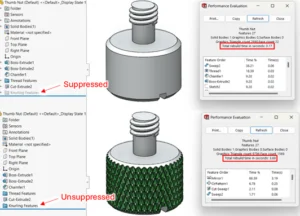
Knurling features can have a significant and sometimes extreme impact on rebuild time, and suppressing, rolling back or even freezing (for use in assemblies) the associated features can alleviate this impact.
Conclusion
Knurling is a very common functional feature found on all sorts of everyday objects, and modeling it can be a fun and necessary challenge, especially on cylindrical designs. Performance implications are important to consider, however, so even once you’ve mastered knurling, you’ll want to consider whether you actually need to model it (definitely yes for 3D printing, maybe not for traditional manufacturing) and take advantage of options like Geometry Pattern and tools like Suppress, Rollback and Freeze to ensure future edits and revisions don’t become an impossibility.
Thanks for reading and happy modeling!