

What separates the average machine designer from an expert designer? The work speaks for itself when everything fits together like it is supposed to. If you have ever witnessed someone bang or smack sheet metal parts to get the desired fit, then let’s take a look at how SOLIDWORKS Sheet Metal tools can trivialize some of the most common issues and productivity sinks when manufacturing sheet metal parts.
Flats being produced come out wrong or inconsistent!
This is by far one of the most common problems using SOLIDWORKS sheet metal can solve!
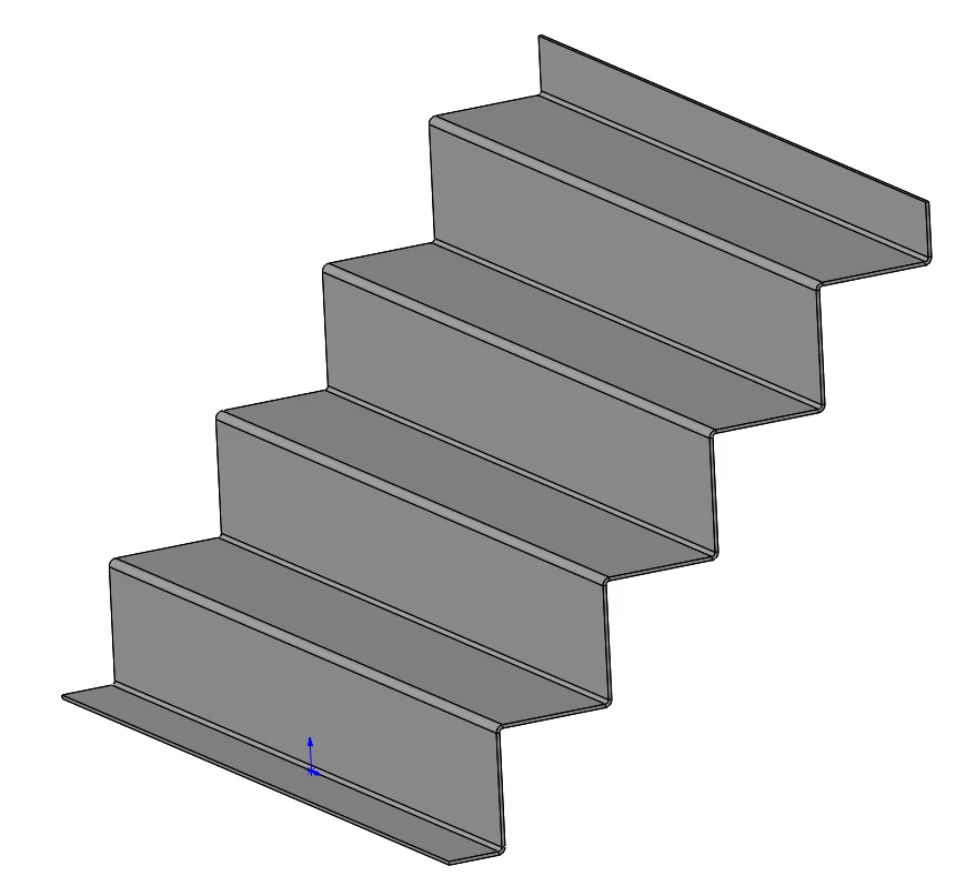
Metal grows when you bend it. The nuances and calculations as to how much varies between tool diameter, metal properties, and thickness. In this day and age there are still shops out there that don’t use them and just eyeball everything. Inevitably, mistakes happen and scrap piles up as designers try to wing it or fabricators try to ding it back into proper place. No more wing and ding!
The best way to get a consistent product is to use the built in tables in SOLIDWORKS. Spend some time setting them up and using them for every part. SOLIDWORKS can calculate and foreshorten the flats appropriately using these tables. While this may seem trivial for some parts, once a part is bent more than 2-3 times it becomes impossible to “wing it.”
For example, see Figure 1 below. Take a simple part geometry like this and do it without proper bend deductions – and the result will be a crooked part every time.
Fit and assembly – parts do not align properly
This stems from many possible issues that are often overlooked. Here are some of the most common ones:
Designers often don’t pay attention to whether flanges are inside or outside flanges when parts mate together and neglect the flange thickness when modeling tolerances in the design. This issue leads to painful stack up errors making parts too long or too short. Compound this with bend deduction issues and a pile of scrap is imminent.
Most designers are familiar with bottom up modeling where a pile of sheet metal parts are created individually and then assembled later.
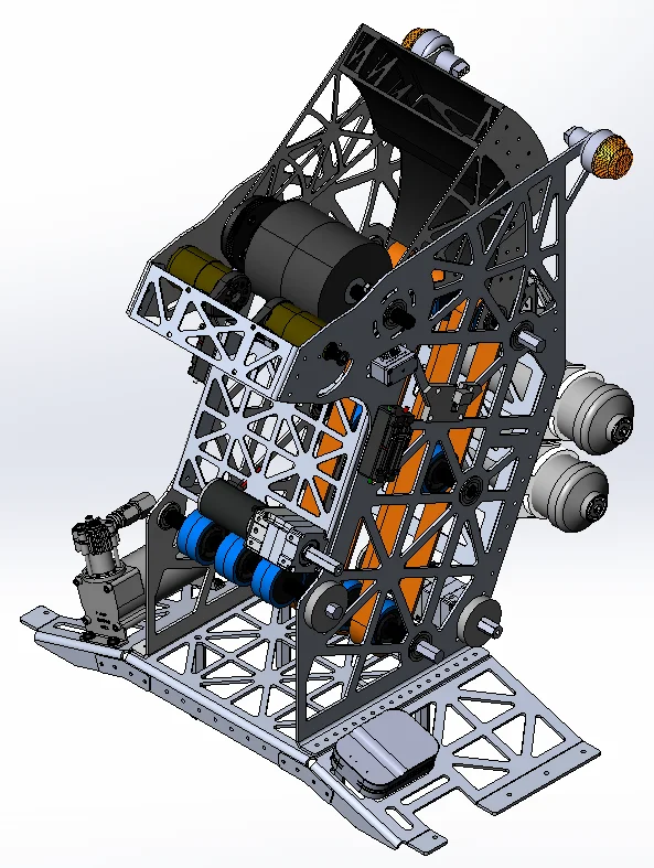
To be frank, most sheet metal assemblies benefit from being constructed in a top down format when it really matters for tolerance because each component can be built in place to create the perfect fit. Hole alignments, flange orientation, notching, coping, and mitering components is much easier when all of the parts are designed in a multi body part format. When flanges and geometry start to stack up, this method of creating parts becomes the much more efficient method to creating sheet metal assemblies because users won’t need to tab back and forth to all of these little parts to make adjustments. When parts need multiple alignment points like this assembly below (Figure 2), top down modeling to place holes and flanges makes way more sense.
Complex Cornering – closing up gaps and getting the perfect miter
Gaps. Holes. Filling the part full of weld and grinding it out because someone couldn’t figure out the folded up geometry of that one little spot. This is a common and painful thing that many companies overlook. How much time are the fabricators patching up mistakes known or not behind the design team that have labor costs and reduction of quality?
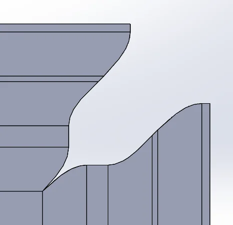
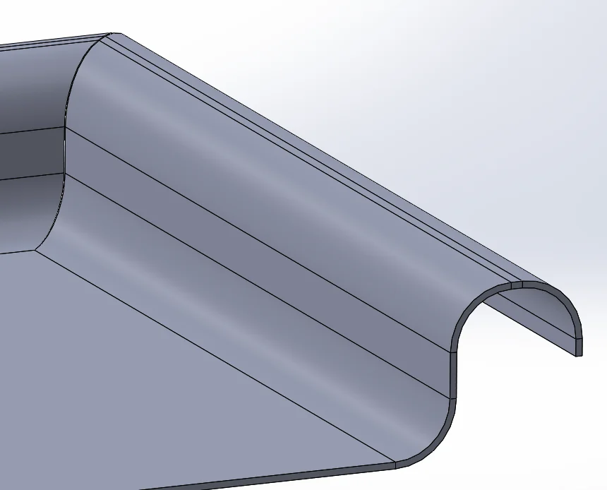
Complex miters are also no joke. The majority of designers cannot do this manually in 2D to make a good flat and SOLIDWORKS can do it with ease using the Miter flange command. See figures 3 and 4. If the gaps are not tight enough, flattening and modifying the notches in the corner will provide one of the fastest and most accurate ways to make the perfect shape to reduce all that labor.
Exporting to CNC using DXFs
Sending parts to out for fabrication has never been easier with SOLIDWORKS and streamlining the entire manufacturing process should be a top goal for companies that have invested in this technology.
Creating a good flat using all of the considerations listed above and exporting it to a .DXF file is as simple as a right click on the part face that is flattened. There are even a number of partner products that will pull all flat patterns out of a folder, create dxf files, and allow batch nesting of components that minimize scrap in one fell swoop.
Too often do companies still save and modify DXF files and route code using 2D software and tools even if the flat was generated in 3D using SOLIDWORKS. SOLIDWORKS has the ability to tie in with several nesting products and take immense time out of the process of modifying these DXF files and creating tool paths to cut out these flats. Doing it the old way is incredibly laborious and companies can save the most money with careful investments in the right nesting solution that helps SOLIDWORKS communicate manufacturing data to those machines.
Speaking of connectivity, most CNC brake software partners in SOLIDWORKS can automatically pull bend line information into the machine without the users or operators doing anything at all. Lift the metal and hit the pedal.
Another common concern is that punch tools are still inserted manually in 2D environment or manually added to the .DXF file in the CAM software for the punch but most of these can actually accept the data that SOLIDWORKS can generate in the DXF file to skip this process entirely! This saves an immense amount of time when dealing with large patterns because the time to manually click or find the punch locations can lead to missed hits and issues in production from user error.
If you can capture all of this information and design your parts with manufacturability in mind your productivity will soar. This is what separates a good machine designer from a great one because you don’t want your legacy measured in scrap unless that pile is empty!