
Working with CAD models created in other systems is always a challenge. Any time you transfer a model from CAD system “A” to CAD system “B” there can be issues. Think of it like trying to translate a complex poem from one language to another. Sometimes there will be a loss of meaning in translation.
Similarly, when we read in a model from another CAD system into SOLIDWORKS, there can be issues as well. This post will show you how to:
- Identify if you have an issue
- Find out where on the model the issue is
- Fix the issue
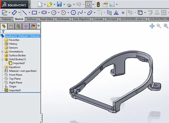
Here is our test case. This was a STEP file that we read into SOLIDWORKS. As you can see by looking at the feature manager, this STEP file has read in and created a solid body.
However, when we try any modeling operations at all, even a simple sketch and extrude, it fails.
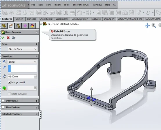
What could be the cause of this? Bad geometry is creating a bad part. Although it looks OK, it is actually invalid. So how do we find out where the problem is? There are actually a couple of ways.
Let’s look at them in detail.
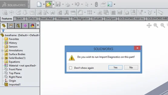
First, when you originally import the STEP file you should see a menu that asks you if you would like to run Import Diagnostics. (If you don’t see this then you may have at one time in the past hit the Don’t show again option). Go ahead and hit the YES button.
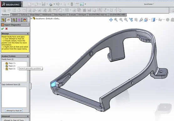
This will show you where the bad surfaces are. If you hover your cursor over the list, you will see a brief description of the issue with the surface. If you hit the big button at the bottom of that menu (Attempt to Heal All) it’s like hitting the easy button and then SOLIDWORKS will try to automatically fix the whole model!
Many times this will work, and your model will be healed and you will be able to continue working with it in SOLIDWORKS. Unfortunately this doesn’t always correct all the surfaces, leaving you with a model you can’t work with.

The way forward is to think of the bad surface(s) in the model like a bad spot on an apple. We are going to take a sharp knife and cut out the “bad” area and replace it with good surfaces, then stitch the model back together and make it whole again.
The knife we are going to use is a command in SOLIDWORKS called Delete Surface. It is in the Command Manager under the Surfacing Tab. Click this command and then pick the “bad” surface.
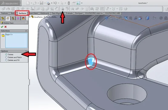
Make sure you look at the options presented to you in the feature manager when you activate the command. You will have three choices.
- Delete
- Delete and patch
- Delete and fill
Let’s explain what each of them does.
The first option will remove the surface and not do anything else. If you pick this option when deleting a face from a solid model you will no longer have a solid model but rather a surface model.
The second option will delete the face and then try to heal or fill the void by extending the boundaries (un-trim or extend) of the adjacent surface. In our case, this option won’t work because extending the bordering surfaces (fillets) won’t give us a spherical corner patch.
The third option will delete the face and use the Filled Surface surface command to try and fill the void by creating a new surface between the open edges left behind after deleting the face(s). This is a powerful option and will often fix the problem area right out of the chute. For the purposes of this article we won’t use this option so that I can show the manual process of repairing imported geometry.
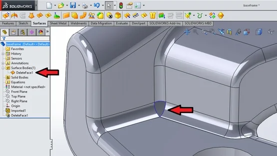
Notice that after we delete the face using the first option, we no longer have a solid model. We now have an open surface model. We know this because of the indication in the feature manager and the blue edges that indicate “open or free edges”. So at this point we have cut out the “bad spot” on the apple. Now we have to fix it by patching it back in.
Even in this simple example there are many different ways to “fix” or re-surface the open spot. To understand all the possible ways this is possible you would have to take the full Surfacing class at Alignex. What I am trying to show is some broad overall steps in the process to fix and repair an imported model, so we won’t spend a ton of time investigating all the methods to do that.
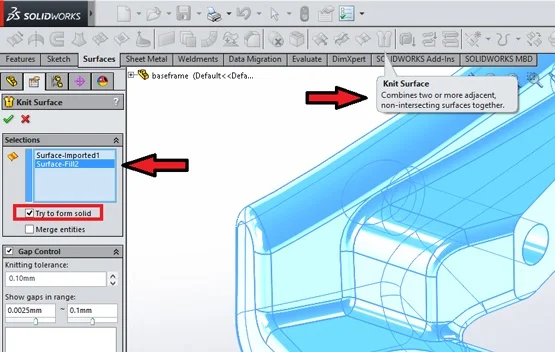
I’ll use one of my favorite commands in Surfacing, the Filled Surface command. This will create a patch surface that, like a Band-Aid, will cover the open spot we just removed. Notice though that we now have two surface bodies, one that was the original part that we deleted the bad face from, and one that is the new surface we just created.
Next, let’s join these two together and try and create a nice solid once again. The command to do this is the Knit Surface command also found in the Surfaces tab of the Command Manager. We pick the command, then select the two surface bodies and pick the option Try to form solid as shown.
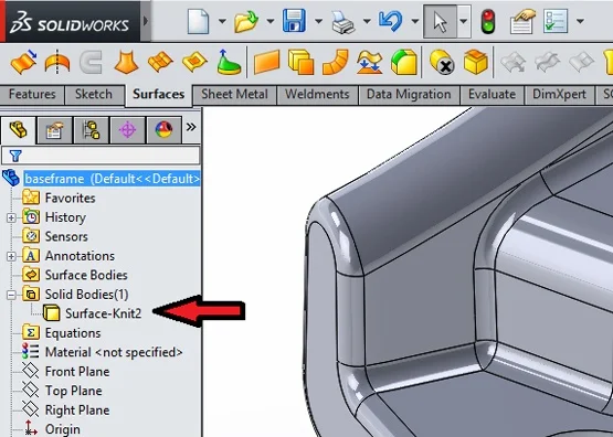
This will give us a nice solid model once again with no more problems.
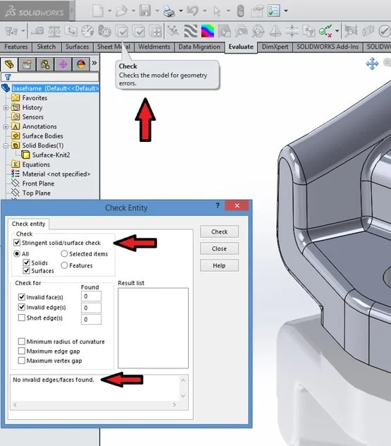
We can check the accuracy and validity of the model by running the command Check found in the Evaluate tab or in the TOOLS->CHECK pull-down text menu. Use the Stringent option always.
So here we are at the end of the process, with a nice clean healthy solid model that we can use to continue our design process. Let’s sum up the steps we’ve followed.
- Run import diagnostics to evaluate the model for validity and to see where the problem surfaces are (if any).
- Use the delete face command to remove the bad parts. You part will be a surface model after this step.
- Use various surfacing commands to reconstruct the bad areas you have deleted.
- Use the knit surface command to rejoin the various patches of surface back together into a solid.
- Run the check entity command to make sure all of the above went well and you have a valid solid.
Keep in mind these are general steps and in any given situation there may be more steps involved. For a much more detailed look at this topic check out the SOLIDWORKS Surfacing class taught at Alignex.
Mack Rasmussen is the Technical Director at Alignex, Inc. and a regular contributor to the Alignex Blog. It’s rare for Mack to have a spare moment between leading Alignex’s team of application engineers and supporting our sales team, but when he does, you’ll most likely find this avid sportsman climbing trees or out hunting and walking a field. Find more tech tips and blog posts by Mack Rasmussen on the Alignex Blog.