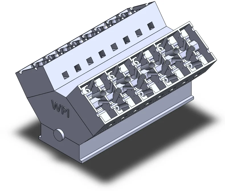

In this final post about the Cylinder Head of the W16 engine I will “repair” the part I made thus far and also adapt it for the right side of the engine.
See detailed explanations in the extended entry at the end of the post.
Download the finished Left and Right Cylinder Ceads.
You can find the previous part of this post here.
Thank you for reading about this build and stay tuned for the next post which will detail the build of the components that go inside the cylinder head and the mates used to connect and make them move.
George Bucsan
Worcester Polytechnic Institute
Aerospace Engineering, 2014
The first time I copied the sketch from the top of the block onto a new part to start creating the cylinder head I did not pay attention to the plane used and I did not check the sketch before starting the build. Because of this, I initially got the part I described in the last two posts: a cylinder head in which the first cylinder is on the right side, whereas the first cylinder in the block is on the left side.
The build of the part thus far required a lot of effort, therefore I chose to modify it rather than create it again from scratch. I thought that if I just make all the part longer and change the settings on the linear patterns to make the cylinder head for 10 cylinders instead of 8 I can then cut it and extrude ribs on the sides to get it to fit.
I modified the length of the main extrude, set all the linear patterns to 5 instances and created the intake/exhaust galleries for the 9th cylinder.
I made an extruded cut on the front face of the part, 4’’ deep, to get rid of the first cylinder. By sketching on the resulting face and converting the outline as an entity I got the outline for the boss-extrude that makes the part perfectly fit the front side of the block (lengthwise). I obtained the depth of this extrude by fitting the intermediate part to the block and measuring the distance between the front surfaces. I then “sealed” the front face of the part with a rib. Through an identical procedure I modified the back side of the part, and with another cut extrude I rebuilt the half-bearings for the camshafts.
For the right side of the main engine block I just modified the parameters of the boss-extrudes created earlier because the basic layout of the cylinders is the same.
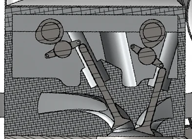
In the picture above you can see how the camshaft pushes the fingers down and how the fingers push the valves down. Each camshaft serves two lines of fingers that represent the intake for the cylinders on one side and the exhaust for the other cylinders.
The next section of the build of this part regards the holes for the rocker finger attachement axles. Each series of valves has a series of fingers, therefore there are four series of fingers that are hit by only two camshafts.
I found the locations of the attachement axle holes through geometrical construction on a sketch. I started the sketch by converting the outline of the camshaft bushings (cuts) and overimposing a circle onto them. By doing measurements and scaling the reference file I was able to estimate the length of the rocker fingers and the diameter of the finger rollers, and to transpose that onto the sketch. I created a circle that is tangent to the circle representing the camshafts and represents the rollers. I then used that roller outline’s center to make a line that stands for the finger and a small circle on that line to show the attachement axle. Also, I projected the outlines of the valve cuts and put centered axes through them to represent the valves. At this point the sketch looks like this:
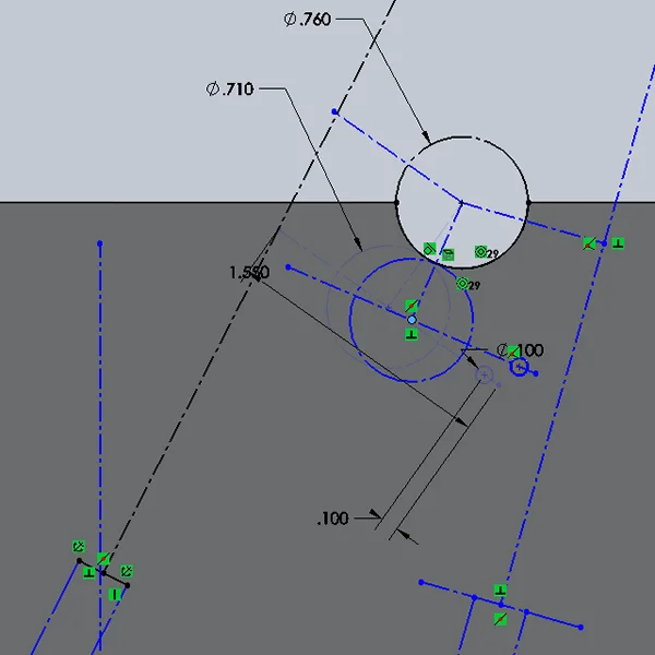
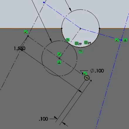
As you can see, the roller is tangent to the camshaft axle and can “swing” in search of a position. The next image shows the finger locked into place and the .100’’ circle that is ready to be used in an extruded cut lengthwise along the cylinder head part. The angle between the finger and the valve (or the lines that represent them) is almost 90 degrees, so that when the finger is going to be hit by the exccentricity of the cam and pushed down, the angle will reach 90 and slightly over, but not reach extreme values (because of the fixed length of the finger, if it rotates too much it does not touch the head of the valve anymore).
At this point, the construction of the cylinder head is complete.
In this part of the build parameters had to be first taken from the reference file and then adapted to fit the virtual model. Parts have been adjusted in small increments to make everything fit, therefore they are probably not that close to the real values but they do the work of showing the movements of the parts inside the cylinder head. To be more specific, because I had to make only one finger that would fit all the 4 lines, I modified the length and the roller diameter to allow the angles between the fingers and the valves to be withing acceptable values, as explained above.
Another parameter I had to keep in mind and adjust in front wireframe view was the clearance: the fingers needed to have enough space to move without hitting/touching anything else but the cams and valves. Also the cuts needed to not go through the sparkplug shafts or the valve cuts.
I used this algorithm for determining the position of the holes of the second line of fingers served by this camshaft and then mirrored these two positions onto the left side of the part. Through extruded cuts I created the holes.