

After teaching 1000’s of students and writing about SOLIDWORKS and SOLIDWORKS Simulation, David Planchard, retired professor WPI, is exploring Design Study, Optimization Analysis and Generative Design. Through this lesson series, David helps educators and their students understand iterative processes through simple examples and industry practices.
With over 28 years of using and teaching SOLIDWORKS, I’m still confused when I hear people say the words, “Generative Design in SOLIDWORKS”. What is Generative Design?
How do you perform an Optimization Analysis in SOLIDWORKS? How does the Optimization Analysis relate to a Design study? What types of design iterations should or can be performed? These and other questions will be explored in a series of lessons.
Time, effort, and skill go into creating a parametric model. The design process starts with selecting the correct sketch plane, utilizing the correct sketch tools, and defining sketch relations. Apply the proper features and end conditions to capture the design intent of the part. Models should be built so changes can easily be made and cost effective to manufacture.
One area where I see students fall short, is performing a parametric study. A study will tell you if the model will fail under a certain load. This can be addressed by decreasing the load, modifying the dimensions, changing material type, moving the load, or a combination of items through iterations.
Over the next series of lessons, we will create Design studies using SOLIDWORKS and SOLIDWORKS Simulation. The Design studies will address the overall mass of the model by performing various iterations on specified design variables while maintaining allowable von Mises stress levels and Factors of Safety (FOS).
In this lesson, open an existing SOLIDWORKS part. Create a Static Linear Simulation study. Apply a Fixed load (Force) and a Fixed Hinge constraint. Mesh and run the study. View the results. Create a Factor of Safety plot. Use the simulation study results to create the first Design study iteration.
The Simulation lesson provides a foundation to users who are new to using simulation to solve real-word engineering and design problems. A Solid body is used. SOLIDWORKS Simulation Premium is included in the SOLIDWORKS Education Edition. You should have a basic understanding of Stress and the Finite Element Method (FEM).
Start SOLIDWORKS
Start a SOLIDWORKS session from your desktop.
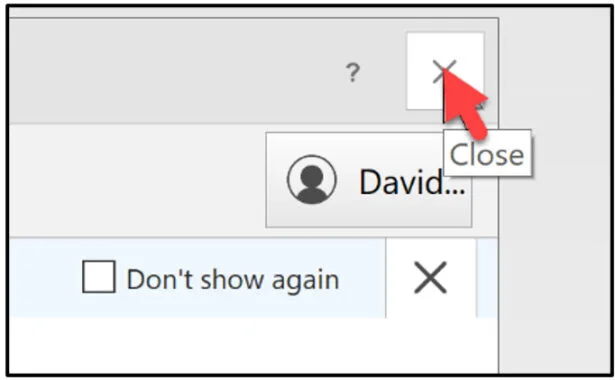
Double-click the SOLIDWORKS 2025 icon. The Welcome – SOLIDWORKS dialog box is displayed.
Close the Welcome dialog box.
Download and Open Cantilever_Bracket Part
Download the SOLIDWORKS Cantilever_Bracket part to follow along with this lesson.
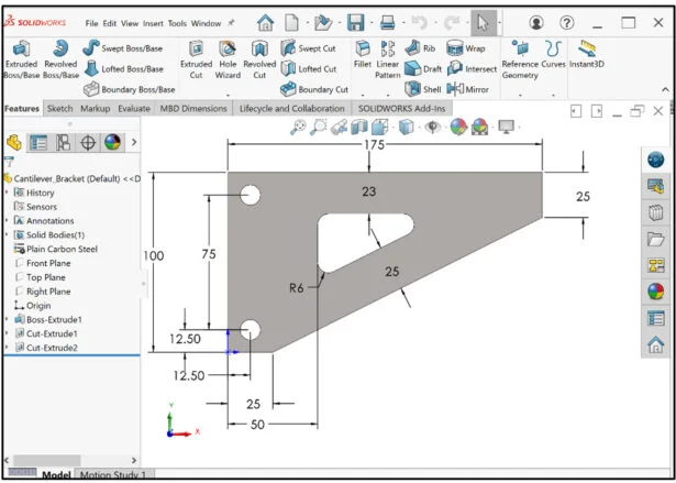
Open the SOLIDWORKS Cantilever_Bracket part.
View the Part FeatureManager.
Linear Static Study in SOLIDWORKS Simulation
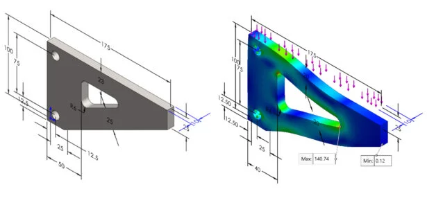
Create a Linear Static Simulation study. The static study information will be used in the Design study. Apply a 8000 N force (1800 lbf) to the top face of the Cantilever_Bracket. Apply a Fixed Hinge restraint to the two inside faces of the holes. Create four plots: Stress, Displacement, Strain and Factor of Safety. View and use the results for a Design study.
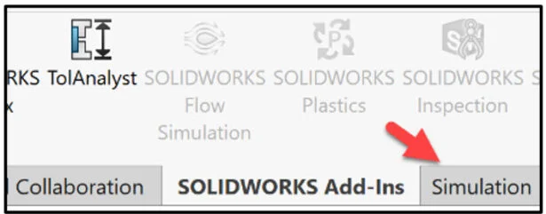
Click SOLIDWORKS Add-Ins from the CommandManager.
Click SOLIDWORKS Simulation.
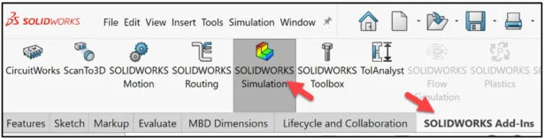
The Simulation tab is displayed.
Click the Simulation tab in the CommandManager.
Create a Linear Static Simulation Study.
Click New Study from the New Study drop-down menu.
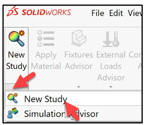
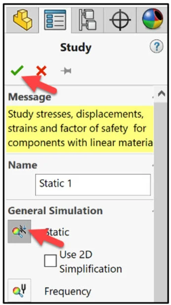
The Study PropertyManager is displayed.
Select Static for General Simulation. Note: A Static study calculates the response of the model on which loads are applied slowly. The loads remain constant after reaching their full magnitudes.
Click OK from the Study PropertyManager.
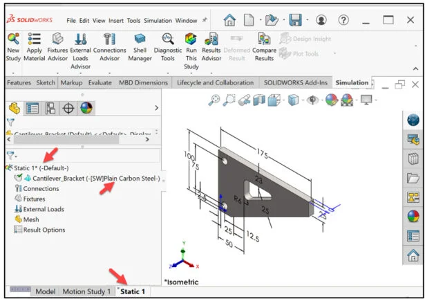
Static 1* study is displayed. Material is Plain Carbon Steel defined from the Cantilever_Bracket model in SOLIDWORKS.
Fixtures and External Loads
Apply a Fixture to the model. The bracket is supported by two rods mounted through the two circular holes.
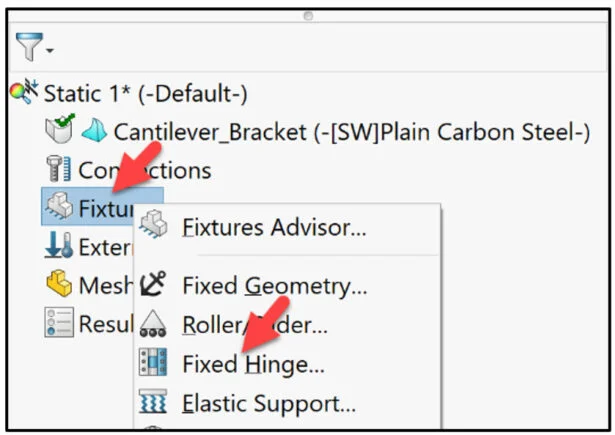
Right-click the Fixtures folder. View the Pop-up menu options.
Click Fixed Hinge.
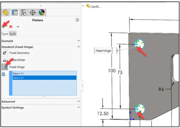
The Fixture PropertyManager is displayed.
Click Fixed Hinge for Standard. The Hinge restraint specifies that a cylindrical face can only rotate about its own axis. The radius and the length of the cylindrical face remain constant under loading.
Select the inside face of the two holes as illustrated. Face<1> and Face <2> are displayed in the selection box.
Click OK from the Fixture PropertyManager.
Fixed Hinge-1 is displayed in the Static 1* study.
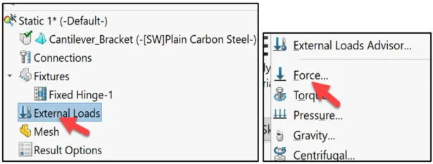
Apply an External Load (Force). The Force/Torque PropertyManager applies forces, moments, or torques with uniform distribution to faces, edges, reference points, vertices and beams in any direction for use in structural studies.
Right-click the External Loads folder in the study.
Click Force from the Pop-up menu. The Force/Torque PropertyManager is displayed.
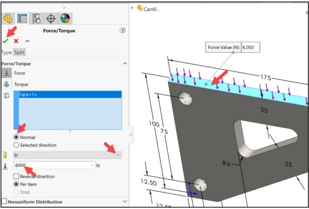
Select the top face of the beam as illustrated. Face<1> is displayed in the selection box.
Click Normal.
Enter 8000N for force.
Click OK from the Force/Torque PropertyManager. Force-1 is displayed in the Static 1* study.
Mesh and Run, View Results
Mesh and Run the study. Use the default mesh standard.
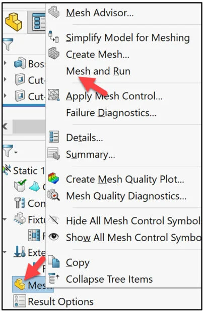
Right-click the Mesh folder from the study.
Click Mesh and Run from the Pop-up menu.
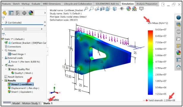
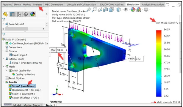
View the created Results folders. The von Mises (N/m2) plot is displayed. The material yield strength is 2.206e+08.
Modify the display of the plot. Modify the units, number display, and number of decimals. Display Max/Min plot number on the model.
Create von Mises and Factor of Safety Plots
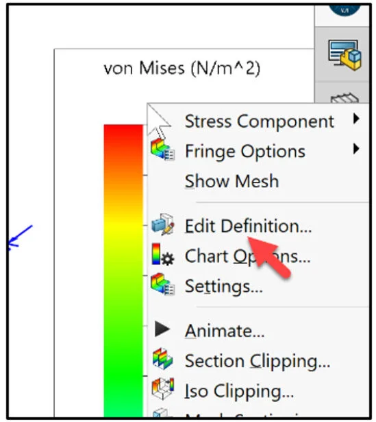
Right-click in the von Mises plot area as illustrated.
Click Edit Definition. The Stress plot PropertyManager is displayed.
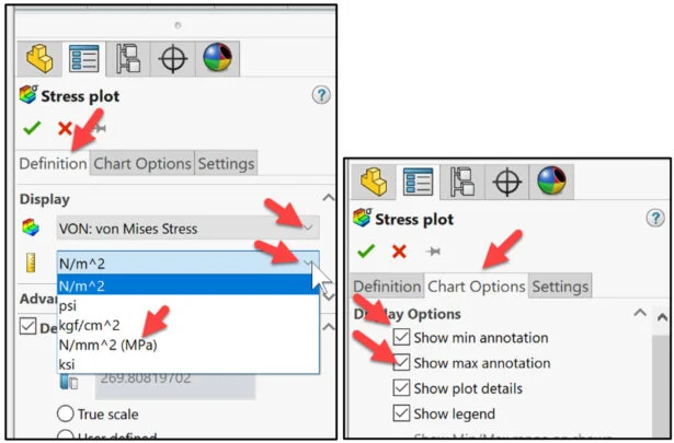
Click the Definition tab. Select VON: von Mises Stress for Display.
Click the drop-down menu. View the unit options. Select N/mm2 (MPa).
Display the Max/Min von Mises Stress on the model.
Click the Chart Options tab.
Click the Show min annotation box.
Click the Show max annotation box.
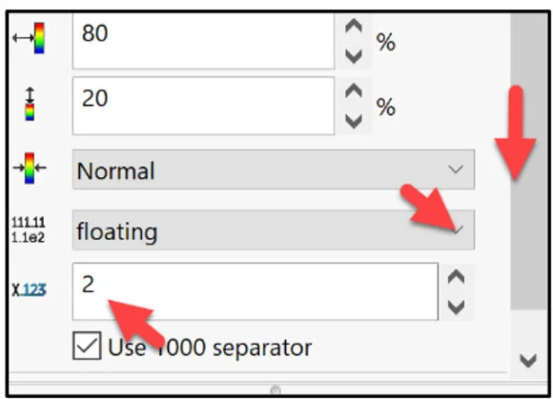
Modify the number format and number of decimals.
Slide the slider bar downward as illustrated
Select floating for number format.
Select 2 for number of decimals.
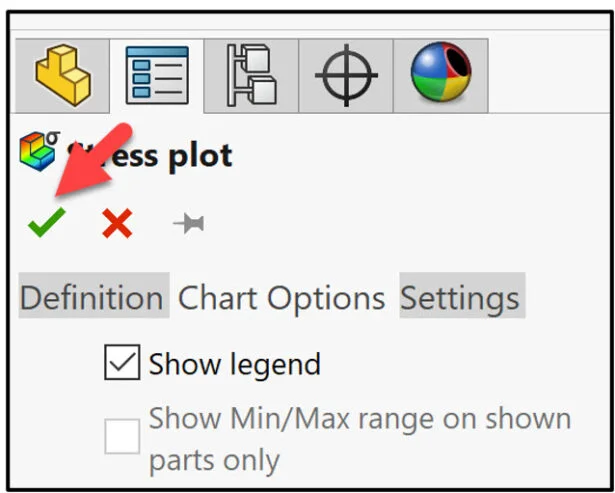
Click OK from the Stress plot PropertyManager.
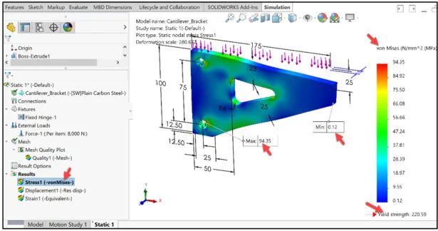
The maximum von Mises stress is 94.35 MPa. The minimum von Mises stress is 0.12 MPa.
The material (Plain Carbon Steel) von Mises stress is 220.59 MPa. This means that the part can have material removed from the Extruded-Cut1 sketch to make the model lighter. This also means that the part can become too weak, but a limit will be set for the part strength.
Create a Factor of Safety plot.
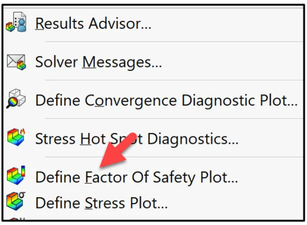
Right-click the Results folder.
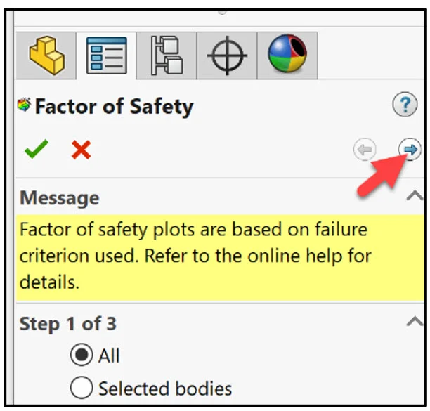
Click Define Factor Of Safety Plot from the Pop-up menu. The Factor of Safety Wizard allows you to assess the safety of your design based on a failure criterion.
When you select All, the stress limit of each component is considered. In an assembly, Factor of Safety is not calculated for components that have no stress limit defined. Such components are grayed out in the Factor of Safety plots. Accept the default settings. Click Next.
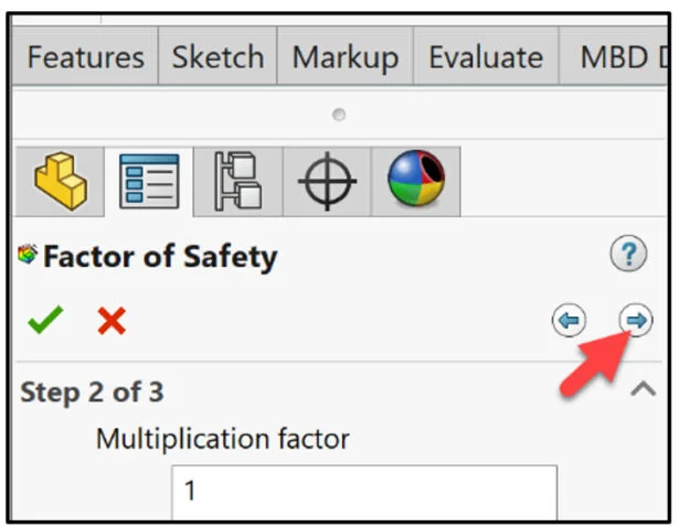
Accept the default settings. Click Next.
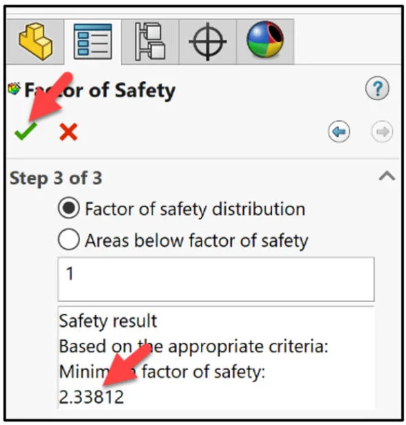
The FOS is 2.34
Click OK from the Factor of Safety PropertyManager. In engineering, a factor of safety (FOS) expresses how much stronger a system is than it needs to be for its specified maximum load. Safety factors are often calculated using detailed analysis because comprehensive testing is impractical.
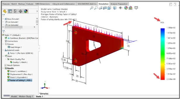
View the Factor of Safety plot. The minimum FOS is 2.34. In general, a structure with an FOS of exactly 1 will support only the design load and no more. Any additional load will cause the structure to fail. A structure with a FOS of 2 will fail at twice the design load.
Return to the von Mises stress plot.
Click the Stress1 (-vonMises-) folder.
Create a Design Study
For an Optimization Analysis, Simulation studies provide extremely beneficial information.
A single simulation study does NOT reveal how to optimize a product. Various iterations should be performed. SOLIDWORKS Optimization analysis tools allow the student to create a series of simulation studies that vary model dimensions, material, loads, constraints, and goals in order to accomplish an engineering design.
Create a Design Study in SOLIDWORKS that is used to create the Optimization Analysis. The goal in this design study is to minimize mass of the model, by varying the dimensions of the Extruded-Cut1 sketch and maintaining structural integrity.
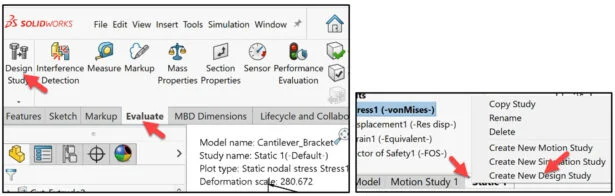
Click the Evaluate tab in the CommandManager. Click the Design Study tool.
Note: You can also right-click the Static 1 tab, click Create New Design Study.
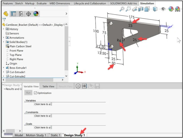
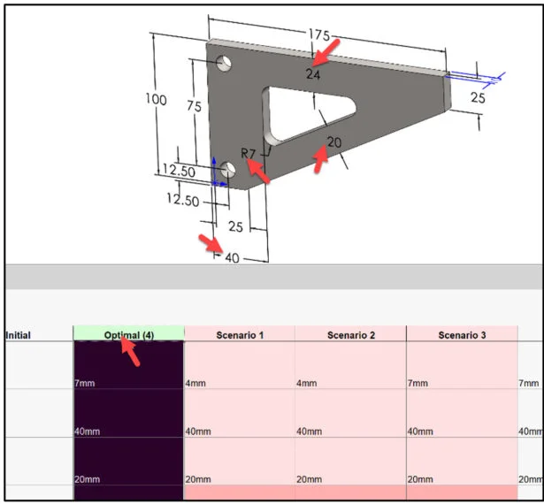
View Design Study 1. For this model, select four dimensions that control the size of the Extruded Cut1 sketch as variables to lower the overall mass of the model. Apply a range of values (Max/Min) to the selected dimensions.
Define Variables, Constraints and Goal for Optimization
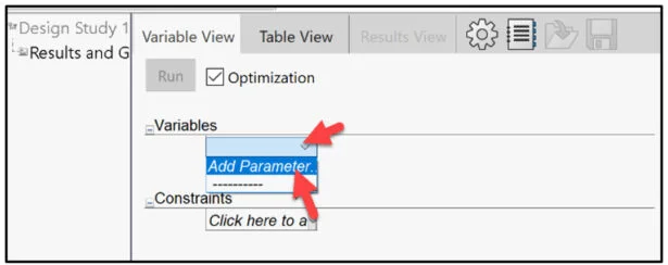
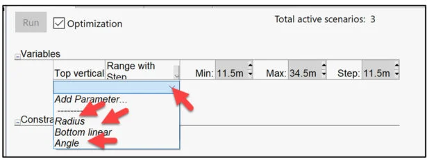
Add the first variable. Click in the First Variable drop-down box.
Click Add Parameter.
The Parameters dialog box is displayed. You can add, edit, or delete parameters in this location.
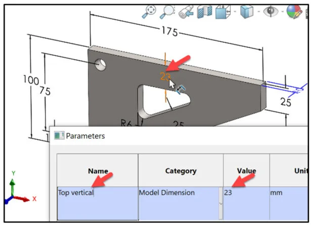
Click inside the Value box. Click the vertical dimension (23) in the Graphics area. 23 is displayed in the Value box.
Enter Top vertical for Name. Press the Enter key.
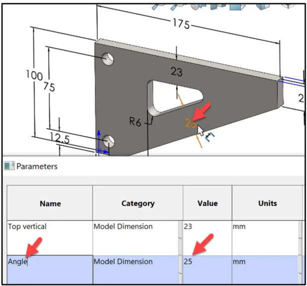
Click inside the Value box. Click the angle dimension (25) in the Graphics area. 25 is displayed in the Value box.
Enter Angle for Name. Press the Enter key.
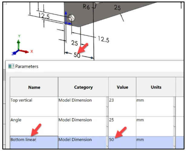
Click inside the Value box. Click the linear dimension (50) in the Graphics area. 50 is displayed in the Value box. Enter Bottom linear for Name. Press the Enter key.
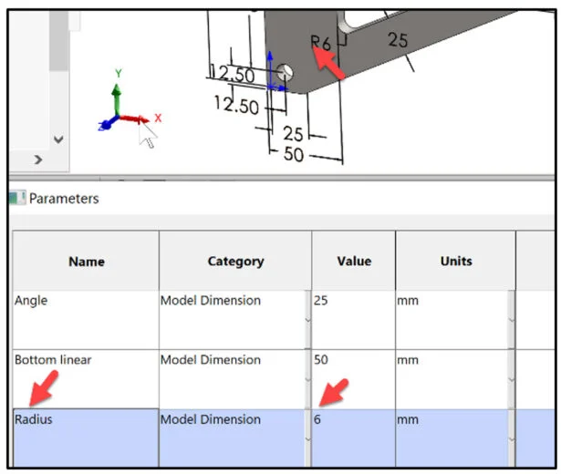
Click inside the Value box. Click the radius dimension (6) in the Graphics area. 6 is displayed in the Value box. Enter Radius for Name. Press the Enter key. Click OK from the Parameters dialog box.
Top vertical is displayed. Select the Radius, Bottom linear and Angle parameter from the drop-down menu as illustrated.
View the results.
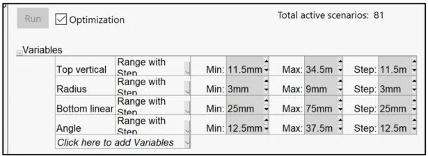
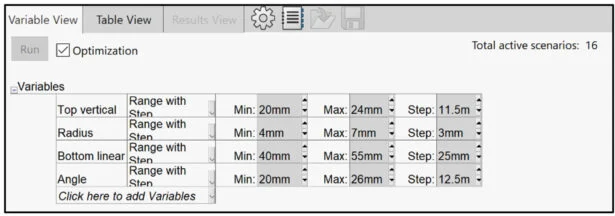
Next enter the Min and Max range for each variable. This is the first design iteration. Limitations of the model and the Extruded Cut1 sketch dimensions are required. I will start with conservative numbers.
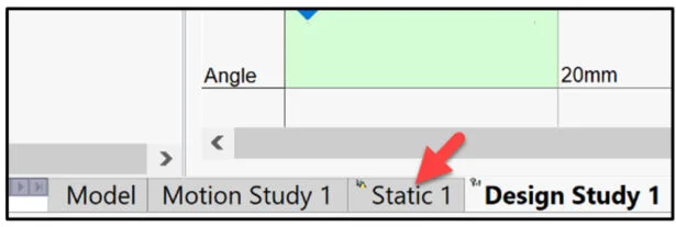
Enter 20mm Min and 24mm Max for Top vertical. Accept the default step value.
Enter 4mm Min and 7mm Max for Radius. Accept the default step value.
Enter 40mm Min and 55mm Max for Bottom linear. Accept the default step value.
Enter 20mm Min and 26mm Max for Angle. Accept the default step value.
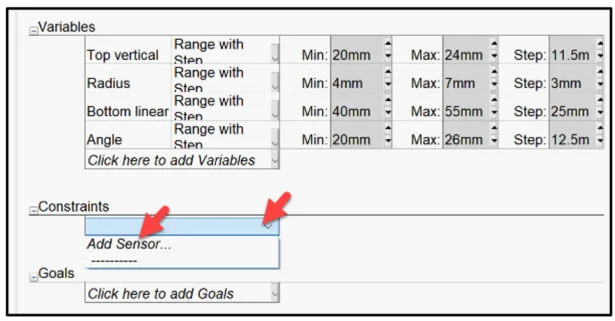
Add a Constraint for the Design Study. In this iteration, I will keep the internal stress under 120 MPa which will provide a Factor of Safety of approximately 2.03. This is an area that you can perform various iterations depending on your application.
Click the Constraints drop-down arrow.
Select Add Sensor.
The Sensor PropertyManager is displayed.
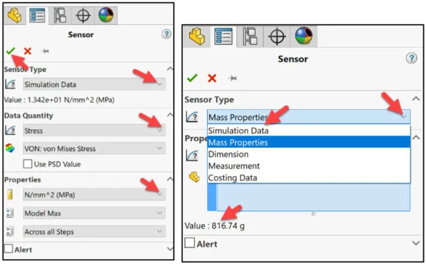
Select Simulation Data for Sensor Type. This will use the results from the Static 1* study. View your options. See SOLIDWORKS Help for additional information on Sensors.
Select Stress for Data Quantity.
Select Von: von Mises Stress.
Select (MPa) for Properties.
Click OK from the Sensor PropertyManager.
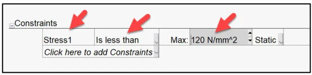
The Constraints table is displayed.
Select Is less than from the drop-down menu.
Enter 120 N/mm2 (MPa) for Max value. Static 1 is selected by default. You can reference various Static studies.
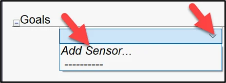
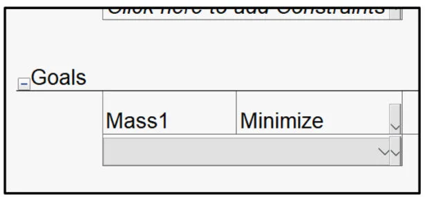
Set the goal to lower the mass of the Bracket.
Select Add Sensor from the Goals drop-down menu.
The Sensor PropertyManager is displayed.
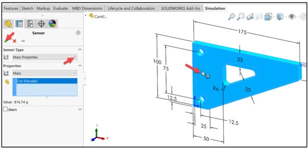
Select Mass Properties from the Sensor Type drop-down menu.
Select Mass for Properties.
Click the model in the Graphics window. The current mass is 816.74 g.
Click OK from the Sensor PropertyManager.
The Goals table is displayed. Minimize is selected by default.
Run the Design Study and View Results
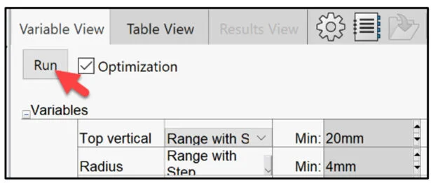
Run the Design study.
Click the Run button to address the size of the cut to maintain a stress less than 120 MPa and a FOS approximately 2.03. Note: Optimization option is required to calculate a Design study with at least one goal.
The Design study ran 18 scenarios. Scenario 4 was the Optimal scenario in this first iteration with the selected parameters, constraint, and goal. The intial mass was 816.74 g. The optimal mass is 758.65 g. You can find a lower mass, but the constraint will be higher. Example: Scenario1 resulted in 719.05 g with a Stress of 175 MPa. Explore the various scenarios.
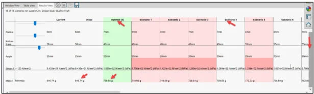
Double-click the Optimal (4) column. The column is active. The model is displayed in the Graphics area with new dimensions (parameters). This is the active model for the Static 1* simulation study.
Return to your Simulation Static 1* study.
Click the Static 1 tab.
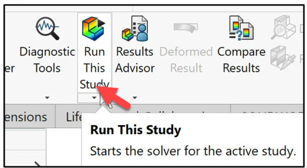
Click Run This Study.
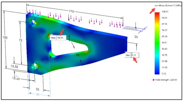
View the von Mises stress plot.
Click the Stress1 (-von Mises-) folder.
The maximum von Mises stress of the initial model was 94.35 MPa. The minimum von Mises stress was 0.12 MPa. The new maximum von Mises stress is 108.91. The minimum von Mises stress is 0.12 MPa.
View the Factor of Safety plot.
Double-click the Factor of Safety (FOS) folder under Results.
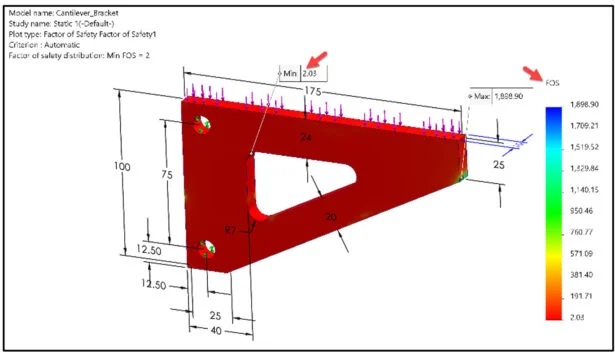
The minimum FOS was 2.34 in the initial model. The new minimum FOS is 2.03.
The lesson is finished.
A single simulation study does NOT reveal how to optimize a product. Various iterations should be performed. SOLIDWORKS Optimization analysis tools allow the student to create a series of simulation studies that vary model dimensions, material, loads, constraints, and goals in order to accomplish an engineering design.
In Lesson 2, we will explore various constraints using Simulation data (Stress, displacement, Factor of Safety) along with modifying parameter variables and goals.
Become a SWUGN Member
SOLIDWORKS and SOLIDWORKS Simulation Educators, register to be part of the SOLIDWORKS User Group Network (SWUGN) with virtual and in person meetings for ever thing about SOLIDWORKS and more.
Additional Resources for Educators and Students – MySolidWorks
You can find additional lessons and learning paths about SOLIDWORKS and SOLIDWORKS Simulation at My.SOLIDWORKS.com.
Design well, Marie