

After teaching 1000’s of students and writing about SOLIDWORKS and SOLIDWORKS Simulation, David Planchard, retired professor WPI, is exploring Design Study, Optimization Analysis and Generative Design. Through this lesson series, David helps educators and their students understand iterative processes through simple examples and industry practices.
In Lesson 1, we opened an existing SOLIDWORKS part. We created a Static Linear Simulation study with an applied Fixed load and Fixed Hinge constraint. We then we meshed and ran the study.
We created a Design study using various parameters (dimensions), constraint (stress from the static study) and set the goal to minimize the mass of the bracket, keeping the outer dimensions constant, while ensuring structural integrity.
The Static 1* study was run with the Design study optimal scenario. Finally, we viewed the von Mises stress and Factor of Safety of the part.
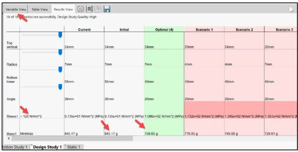
In Lesson 2, open the previous SOLIDWORKS model, Static Study *1, and Design Study 1 from Lesson 1. Before deciding on an optimized design, explore the numerous options and iterations. Modify the Constraint from Stress (less than 120 N/mm2 (MPa)) to a Factor of Safety (greater than 1.2). The goal is the same, to minimize mass of the model, by varying the dimensions of the Extruded-Cut1 sketch and maintaining structural integrity. Re-run Design Study 1 with the new Constraint. View the result of the mass (758.65 g – 719.05 g) a reduction of 39.6 g.
Save Design Study 1 in a .csv format. View the Excel file. Copy the existing Design Study. Save and close all studies.
The Simulation lesson provides a foundation to users who are new to using simulation to solve real-word engineering and design problems. A Solid body is used. SOLIDWORKS Simulation Premium is included in the SOLIDWORKS Education Edition. You should have a basic understanding of Stress and the Finite Element Method (FEM).
Start a SOLIDWORKS session from your desktop.
Double-click the SOLIDWORKS 2025 icon. The Welcome – SOLIDWORKS dialog box is displayed.
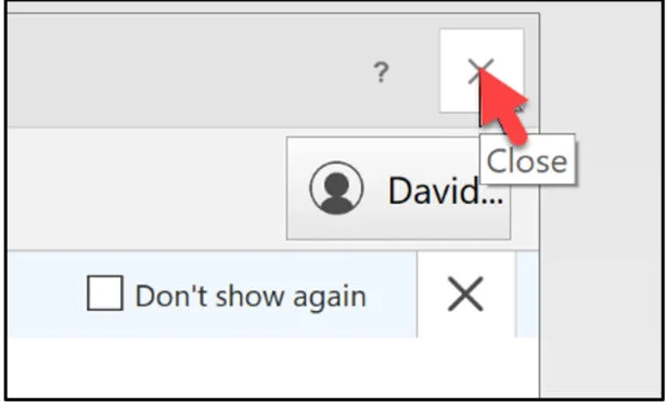
Close the Welcome dialog box.
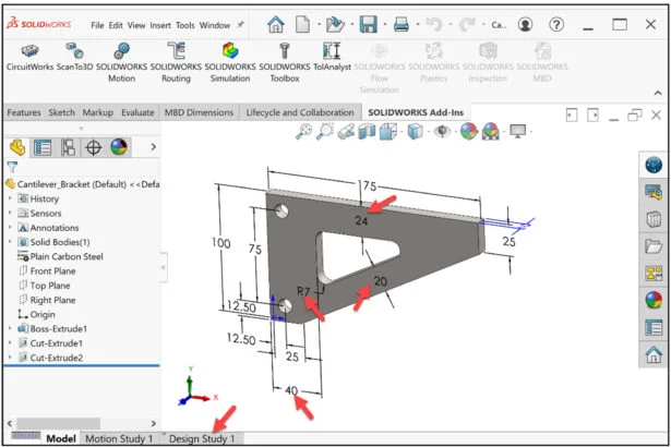
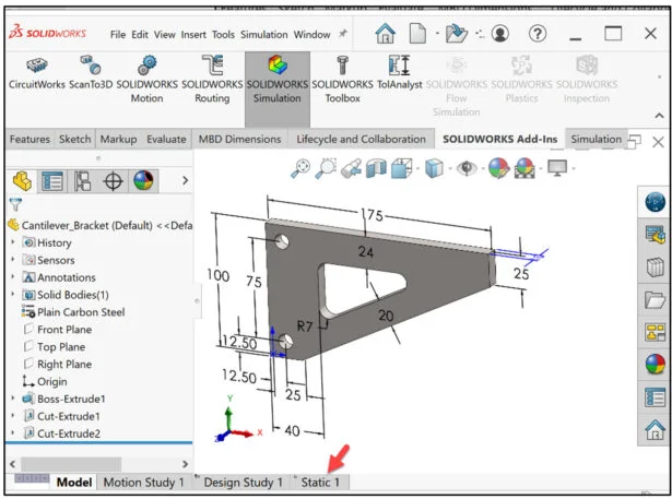
Open the SOLIDWORKS Cantilever_Bracket part, Design Study 1, and Static Study 1 you created in Lesson 1.
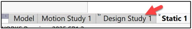
View the Part FeatureManager. The Design Study 1 tab is displayed.
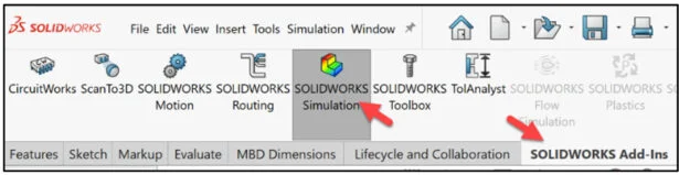
Click SOLIDWORKS Add-Ins from the CommandManager.
Click SOLIDWORKS Simulation.
Linear Static Study in SOLIDWORKS Simulation
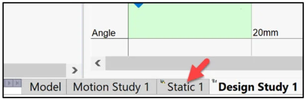
The Static 1 tab is displayed below.
Display the Static 1* study from Lesson 1.
Click the Static 1 tab.
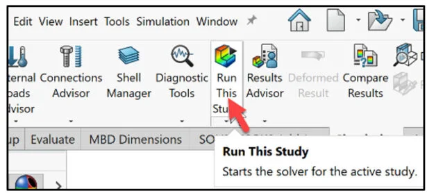
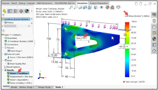
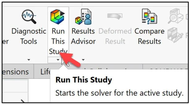
The Static 1* study is displayed. Click Run This Study from the CommandManager.
The maximum von Mises stress of the initial model in lLesson 1 was 94.35 MPa. The minimum von Mises stress was 0.12 MPa. The mass of the part was reduced from 816.74 g to 758.65 g. The new maximum von Mises stress is 108.91 MPa. The minimum von Mises stress is 0.12 MPa.
The minimum FOS was reduced from 2.34 to 2.03.
Return to Design Study 1.
Click the Design Study 1 tab. Design Study 1 is displayed.
Return to the Variable View area.
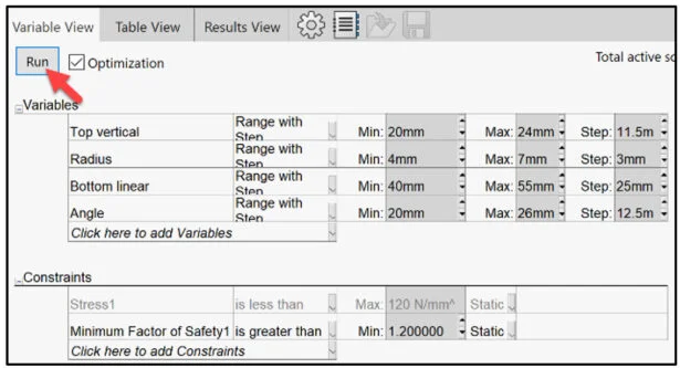
Click the Variable View tab.
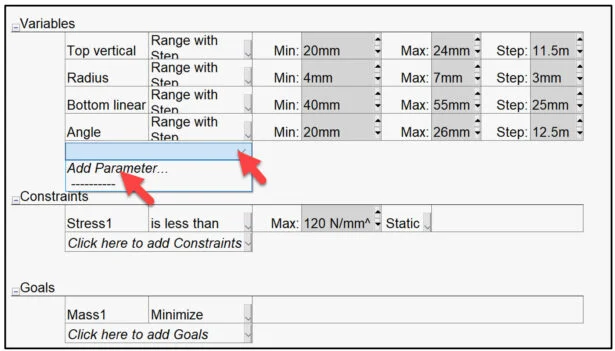
The Variables, Constraints and Goals are displayed.
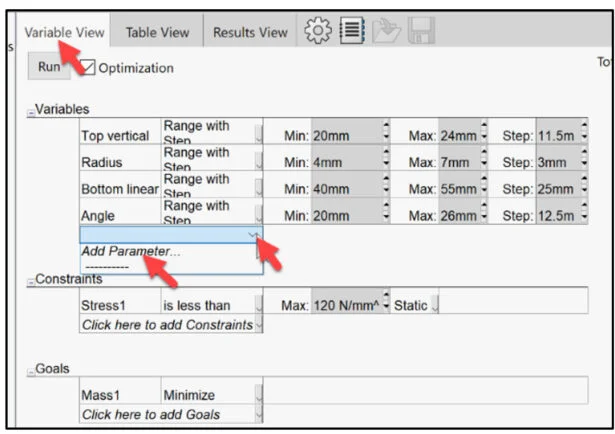
Click the drop-down arrow under Variables as illustrated.
Click Add Parameter.
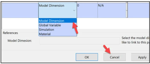
The existing Parameter dialog box is displayed. You can add, edit, or delete parameters in this location.
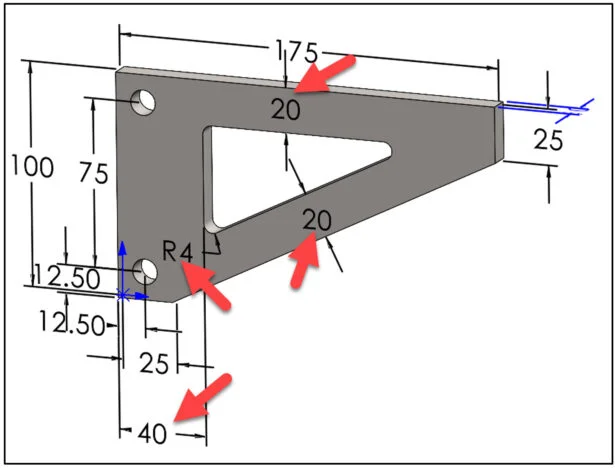
In Lesson 1, we selected four dimensions that controlled the size of the Extruded Cut1 sketch as variables to lower the overall mass of the model. The default drop-down option was Model Dimension.
There are three other options: Global Variable (define global variables in the Add Equation dialog box), Simulation (Study properties, Mesh, Loads, Fixtures, Shells, Contact), and Material (material of single-body or multi-body parts).
Use parameters in Design Studies and link them to variables that can be changed with each iteration of an evaluation or optimization design scenario.
Close the Parameter dialog box.
Click Cancel.
In Lesson 1, we Added a Sensor tied to the von Mises Stress calculated in the Static 1* study. We used a stress less than 120 N/mm2 (MPa).
Add a Sensor tied to the Factor of Safety calculated in the Static 1* study.
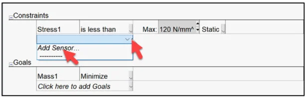
Click the Constraints drop-down arrow.
Click Add Sensor.
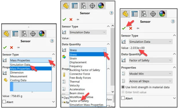
The Sensor PropertyManager is displayed. At this point, the mass is 758.65 g.
Select Simulation Data from the Sensor Type drop-down menu.
Select the drop-down arrow from Data Quantity. View your options.
Select Factor of Safety from the drop-down menu. The current FOS is 2.03
Click OK from the Sensor PropertyManager.
Return to the Variable View dialog box.
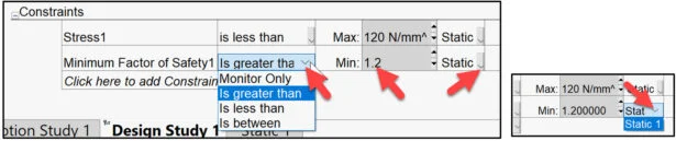
Minimum Factor of Safety 1 is displayed in the Constraints box.
Select Is greater than from the drop-down menu.
Enter 1.2. Static 1 is selected by default. You can reference various Static studies.
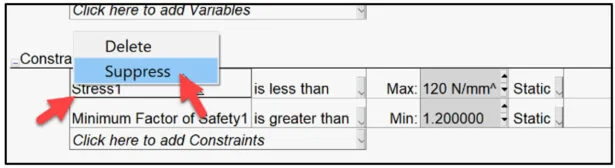
Suppress the Stress1 Constraint.
Right-click in the Stress1 box, click Suppress.
Run the study. Click Run.
View the results.
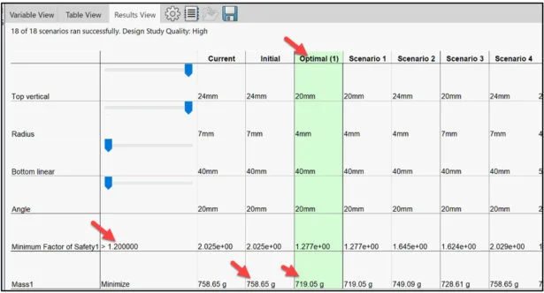
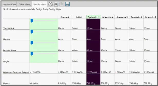
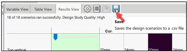
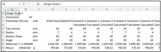
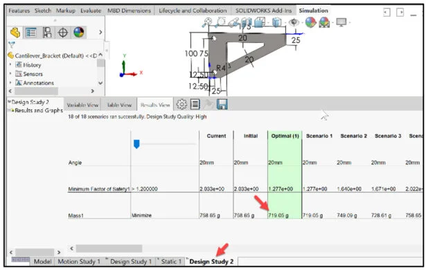
The Design study ran 18 scenarios. Scenario 1 is the Optimal scenario in this iteration with the selected parameters, constraint, and goal. The initial mass of the part was 758.65 g. The new mass is 719.05 g. Explore the various scenarios.
Double-click the Optimal (1) column. The column is active. The model is displayed in the Graphics area with new dimensions (parameters). This is the active model for the Static 1* simulation study.
Return to your Simulation Static 1* study.
Click the Static 1 tab.
Click Run This Study.
View von Mises and Factor of Safety Plots
View the von Mises stress plot.
Click the Stress1 (-von Mises-) folder.
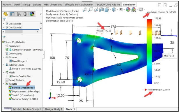
The maximum von Mises stress was 108.91 MPa. The minimum von Mises stress was 0.12 MPa.
The new maximum von Mises stress is 172.93 MPa. The new minimum Von Mises stress is 0.12 MPa.
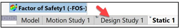
View the Factor of Safety plot.
Double-click the Factor of Safety (FOS) folder under Results.
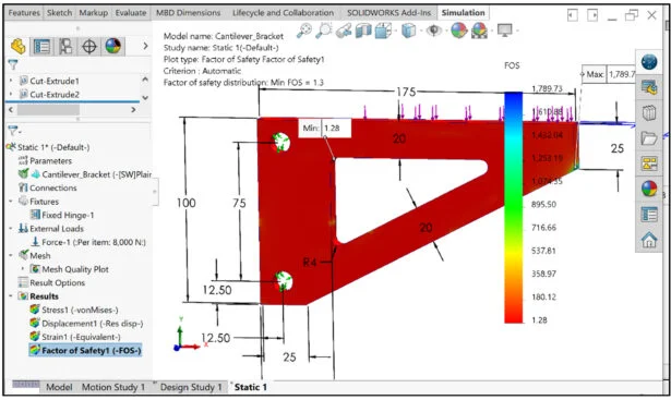
The minimum FOS was 2.03 in the initial model. The new minimum FOS is 1.28.
We reduced the mass by 39.6 g (758.65 g – 719.05 g) with a safety factor of 1.28 by modifying the Constraint.
Save Design Scenarios to .csv file (EXCEL)
Return to Design Study 1. Save the study to a .csv file.
Click the Design Study 1 tab.
Design Study 1 is displayed.
Click Save as illustrated. Save the design scenarios to a .csv file.
The Save As dialog box is displayed.
Select the save folder name.
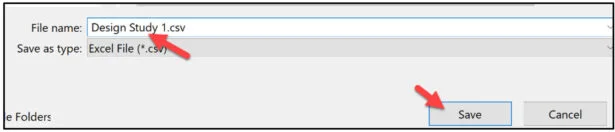
Enter Design Study 1 for File name. Click Save from the Save As dialog box.
Open the Excel file from the save folder. View the results.
Close the Excel file.
Copy the existing Design Study.
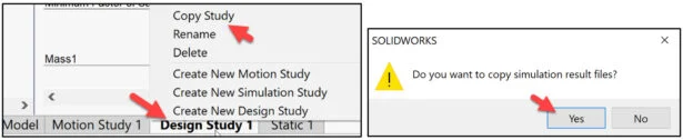
Right-click the Design study 1 tab. View your options.
Click Copy Study.
The SOLIDWORKS dialog box is displayed.
Click Yes.
Design Study 2 is created.
Double-click the Design Study 2 tab. View the results.
Lesson 2 is finished.
In Lesson 3, we will explore Topology Optimization. Topology Optimization is a technique to remove material from a user defined shape or design space to maximize the performance of the space. Performance can mean maximize Stiffness to Weight ratio, minimize displacement, or a combination of both for a given set of loading conditions.
Topology Optimization allows students, designers and engineers to create efficient, lightweight, and structurally sound designs by determining the optimal material layout within a given design space.
Become a SWUGN Member
SOLIDWORKS and SOLIDWORKS Simulation Educators, register to be part of the SOLIDWORKS User Group Network (SWUGN) with virtual and in person meetings for ever thing about SOLIDWORKS and more.
Additional Resources for Educators and Students – MySolidWorks
You can find additional lessons and learning paths about SOLIDWORKS and SOLIDWORKS Simulation at My.SOLIDWORKS.com.
Design well, Marie