
In this post about the W16 Engine I will continue describing the cylinder head’s build up until the point I initially thought it is ready, but then realized it is flipped upside down.
You can find the first part of this post here.
Download the part file.
See detailed explanations in the extended entry at the end of the post.
Thank you for reading about this build and stay tuned for the next post which will continue the with the cylinder head’s „repair” and conversion for the right side of the engine.
George Bucsan
Worcester Polytechnic Institute
Aerospace Engineering, 2014
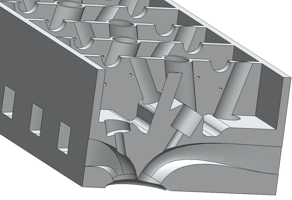
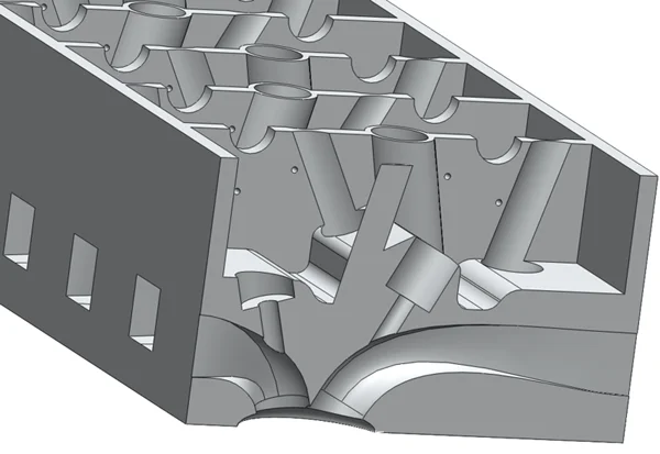
In the previous post I presented the part with the combustion chambers and the valve head holes. Now I will continue with the channels that link the intake and exhaust manifolds with the combustion chambers (see the above picture).
For these I used lofted cuts between sketches on the sides of the cylinder head and sketches from the planes of the valve-head cuts. Using the reference lines on the base sketch from the previous post, I created sketches for each lofted cut. Each sketch is on the right/left side of the part, at a 1.25’’ height and with a side length of 1’’. For each valve hole I had to make one loft, to a total of 32.
At this point I thought it would be the right time to carve out the top side of the part. I started with a 2.25’’ blind extruded cut from a sketch that is .3’’ offset from the top’s outline. Just to keep track, that is Cut-Extrude3.
After that, I started cutting the holes for the valves (the long thin part of the valves, the tails). On Plane8, the plane used for cutting the holes for the heads of the valves, I created a sketch. I centered two holes .31’’ in diameter onto the centers of the first two valve cuts from the first left combustion chamber. Then using a linear sketch pattern with the distance set to 5.3’’ I made another 6 of them, enough for the intake galleries for the four left cylinders. I have to mention also that the lofted cuts going towards the inside of the engine (right side in this case) are intake, and the ones going towards the outside (left side here) are the exhaust. Using Plane7 I made similar cuts to create the exhaust for the four left cylinders.
Enough with the left side, let’s do the same on the right side. I created Sketch60 to create (mirror) the construction lines used for Planes 7 & 8. Using that, I made Planes 10 & 11 and Cut-Extrude7 & 8 (the valve holes).
Now that I have the holes for the valves I can continue with the ribs inside the top part of the “case”. Using the initial base sketch I created a line and with that a Rib. I multiplied that with a linear pattern (guess the distance: 5.3’’).
Through some measurements on the reference file I was able to get the approximate location of the camshafts; therefore I created the cuts for them: two semi-circular cuts on the top part of the cylinder head, .76’’ in diameter, and 1.347’’ from the sides.
Next, I thought it would be the right time to make the cuts for the spark plugs, as they take a lot of space. These are built very roughly, as they only need to represent where the part should be and they do not serve any function in the mechanical movements of this model. Because of this, I will not detail this section extensively.
By some measurements on the reference file I was able to approximate the angle between the spark plugs and the vertical axis. I used Sketch66 to create Plane14, and Plane14 to create Sketch70. I used a construction line on that sketch as the direction for a boss extrude that creates the “tubes” in which the spark plugs sit. Through a circular pattern and a linear pattern, this feature was copied to all eight cylinders.
These “tubes” for the plugs are not ready because they are constructed onto the ribs and they are not hollow inside. I used Cut-Extrude11 to make the thin cut towards the combustion chambers and Cut-Extrude15 to make the cut for hollowing the thick top tubes out. I then used the now classical combination of circular pattern and linear pattern to duplicate these to all the cylinders.
The next step was creating the mountings for the springs. For this, I made this sketch:
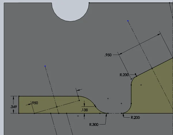
I already knew the width of the springs (.95’’) and the position of the valves (seen on the sketch in construction lines, as converted entities). The left side shows approximately how I cut into this profile after I extruded. The curves used are purely guessed cosmetics in this case and do not interfere with the functional aspect of the part.
Now the holes for the springs: As the springs are concentric with the valves, the cuts for the heads of the valves are a good start. I made a sketch on one of them, created an offset entity to match the width of the springs and extruded cut the sketch. The settings were from an offset and up to a surface – the inner face of the wall of the now box-looking part. I set the offset to 1.66’’ when looking to the part from a front view with a wireframe setting: it leaves enough solid material between the exhaust/intakes galleries and the spring mounting. This item was Cut-Extrude 13; I used the same technique, in the mirror, with Cut-Extrude 14, and then duplicated them to all of the cylinders. At this point, I had the valves on the right and left sides and their spring sorted out.
The boss extrude used for the spring mountings sealed off the valve holes from the middle of the part. For this, I needed to cut through the newly added material. I created an axis: “inner valves” by setting it centered on the previous valve cuts. I used that and a profile from two of those cuts to make Cut-Extrude16 and then duplicate it to all of the cylinders. With the same technique I made the cuts for the springs of these valves and duplicated them.