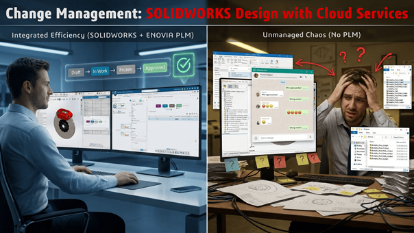
Change Management with SOLIDWORKS Design: Part One
This two-part blog series provides a guide to change management in SOLIDWORKS Design with Cloud...
June 19, 2026

How Structural Simulation Explains Football
Discover how SOLIDWORKS Simulation reveals the engineering behind football’s evolution from heavy leather balls to...
June 18, 2026
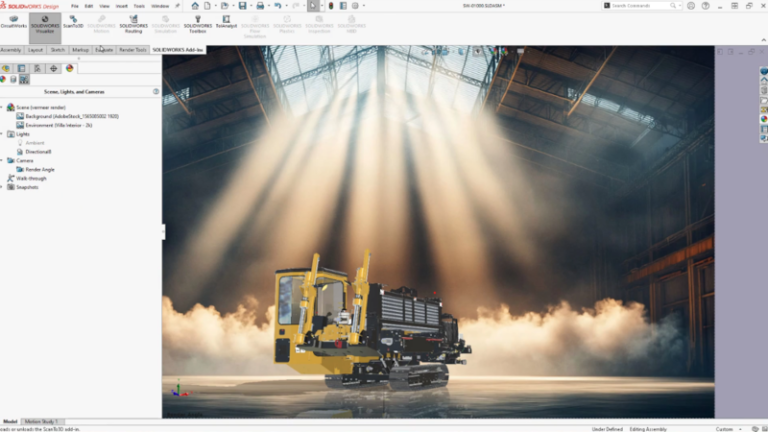
Create an Experience with SOLIDWORKS Design 2026 Visualization...
The latest visualization and rendering enhancements help you create virtual twins of your materials with...
June 17, 2026
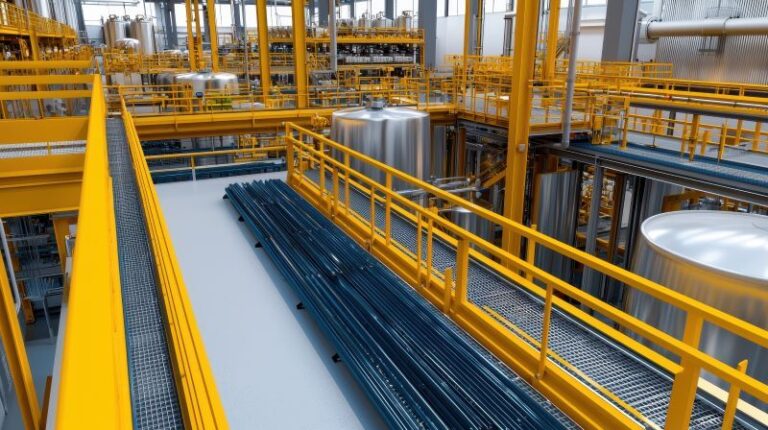
Heavy Metal, Big Challenges: How Industrial SMBs Can...
Discover how SOLIDWORKS Manufacturing Solutions, deployed on the 3DEXPERIENCE platform, helps industrial SMBs replace risky...
June 11, 2026
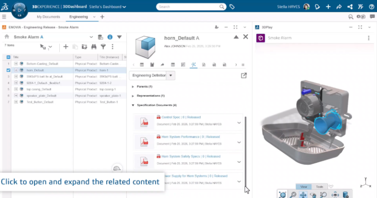
SOLIDWORKS PLM R2026x FD02: Key Updates Across Standard,...
Updates include project planning enhancements, scenario comparison and more.
June 10, 2026
The SOLIDWORKS Automation Triad
Explore this blog to open the door to a whole new world of automation possibilities...
June 8, 2026

A Graduation Cap that Actually Moves
Create a custom graduation cap with moving gears using CAD and 3D printing. Download free...
June 5, 2026
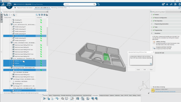
Keep Design and Manufacturing Connected with SOLIDWORKS Machining...
The new manufacturing roles include enhancements for machining efficiency, automation, and better visibility into programming...
June 3, 2026

SOLIDWORKS Start-up CocoTerra – Engineering the Future of...
CocoTerra, SOLIDWORKS Start-up allows you to create your own chocolate innovations.
June 2, 2026