

- For the Flash, we can define Color of highlight, Intensity of the emission and Highlight
- Under Rotate, choose axis of rotation X, Y and Z. Enter value ‘1’ for the axis to make in use. Instead of choosing axis, we pick the axis of the actors. To do so click on Axis > press Alt to pick center of axis of the actor. Of course, for unscrewing we keep the default Angle of rotation 360.
- For the Translate animation, we follow the same method to select axis for direction of translation as mentioned in Rotate animation. Also provided distance of translation.
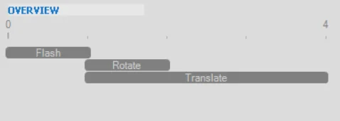
- On every change in parameters the Overview gives a graphical overview of the order of motions in global animation.
 Once the we are satisfied with necessary changes, run the animation.

In the Timeline, check the animation block is created. This block can be expanded, collapsed and even move across the timeline. Animation blocks consists of multiple animation keys restricted to the respective blocks. This avoids the situation of overlapping of multiple animations with individual keys in the Timeline. You can also create multiple animation blocks and manipulate them together.
Now you try the animations from the library and write us in case of query.
3. Understanding the Dirty Mark (*) in SOLIDWORKS®
By Jayendra POTDAR
What is the Dirty Mark?
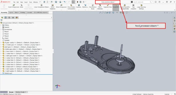
The asterisk (*) next to a file name in SOLIDWORKS indicates that changes have been made to the file but have not been saved yet. It serves as a reminder that the file needs to be saved to retain the changes.
Causes of the Dirty Mark appearing:
- Making geometric changes to a part or assembly: Modifying dimensions, adding features, or changing geometry within a part or assembly can trigger the Dirty Mark. These changes alter the model and require saving to preserve the modifications.
- Failing equations or mates: When equations or mates fail to resolve properly due to changes in geometry or configuration, SOLIDWORKS marks the file as dirty. This prompts users to review and correct these issues before saving.
- Changing system units: Adjusting units within a part or assembly affects dimensions and properties. Such changes trigger the Dirty Mark to indicate that adjustments have been made and need to be saved to maintain accuracy.
- Circular references: Circular references occur when entities refer to each other in a way that leads to an endless loop of dependency. With Circular references, a rebuild occurs and hence a Dirty Mark is triggered.
- Corrupt geometry or inconsistent face IDs: Issues like corrupt geometry or inconsistent face IDs can occur due to modeling errors or importing problems. These inconsistencies trigger the Dirty Mark, prompting users to address and rectify these issues to ensure model integrity.
- Incorrect appearance assignments: Assigning incorrect appearances or materials to faces or components can lead to discrepancies in the model’s visual representation. SOLIDWORKS flags these discrepancies with the Dirty Mark, indicating the need for correction and subsequent saving of changes.
Understanding these triggers helps SOLIDWORKS users effectively manage their design processes, ensuring that changes are properly tracked and saved to maintain the accuracy and integrity of their models.
Behavior Issues with Dirty Mark:
Sometimes, users report issues where the Dirty Mark doesn’t appear despite making changes in the session. This can be frustrating as it might lead to accidentally losing changes if not saved promptly.
Identifying Rebuild Conditions in Assemblies:
- To determine which features or conditions in an assembly require a rebuild, follow these steps:
- Open the assembly in SOLIDWORKS.
- Make changes as desired.
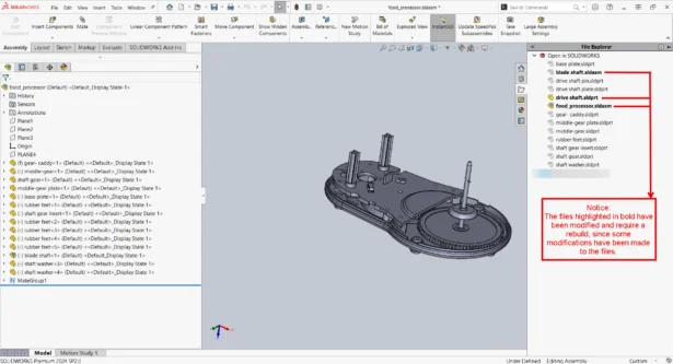
- Use File Explorer and look for files with bold highlights when you use Open in SOLIDWORKS from the Task Pane. Files in bold have been modified and may have a Dirty Mark.
- An assembly immediately displays a dirty mark when it is opened, and even though no changes have been done, SOLIDWORKS prompts us to save data when we try to dismiss the assembly:
- Sometimes, upon opening the assembly, the assembly displays a Dirty Mark (*) icon, as shown below:

- Rebuilding (Ctrl + Q) or force rebuilding (Ctrl + Shift + Q) in SOLIDWORKS initiates updates across the entire assembly.
- However, if there are certain external references are linked to the parent assembly, they get updated automatically each time the assembly is rebuilt.
- This update process triggers the Dirty Mark (*), indicating that changes have been made to the assembly.
- To remove the dirty mark, rebuild the parts or assemblies that contain external references.
- Sometimes, upon opening the assembly, the assembly displays a Dirty Mark (*) icon, as shown below:
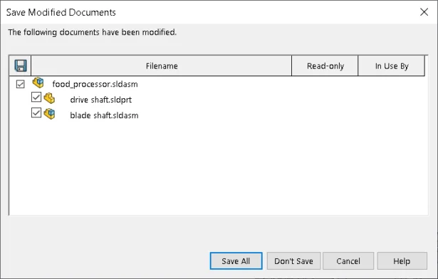
To maintain the most recent modifications, it is always advised that the user saves the document before closing the session.
Addressing Issues with Dirty Mark:
If the Dirty Mark is not triggering correctly after making changes, it could be due to software bugs or configuration issues. Here are some steps to mitigate such problems:
- Upgrade SOLIDWORKS: Ensure you are using the latest version of SOLIDWORKS as updates often include bug fixes.
- Check File Properties: Verify that the files you are working with are not set to read-only or have permissions issues that prevent saving.
- Restart SOLIDWORKS: Sometimes, restarting the software can resolve transient issues with Dirty Marks not appearing.
- Report Issues: If problems persist, report them to the SOLIDWORKS Technical Support so they can investigate and provide a fix in future updates.
You can efficiently manage modifications and make sure your work is correctly saved and recorded in SOLIDWORKS by being aware of potential problems and comprehending how the Dirty Mark (*) functions.
Happy Designing!
Hello to all,
Welcome to the new edition of the SOLIDWORKS® Support Monthly News! This monthly news blog is co-authored by members of the SOLIDWORKS® Technical Support teams worldwide. Here is the list of topics covered in this month’s Blog :
-
Understanding the ‘Replace BOM Items’ Feature in SOLIDWORKS® Manage
-
Working with Predefined Animation in SOLIDWORKS® Composer
-
Understanding the Dirty Mark (*) in SOLIDWORKS®
1. Understanding the ‘Replace BOM Items’ Feature in SOLIDWORKS® Manage
By Rohit MAGAR
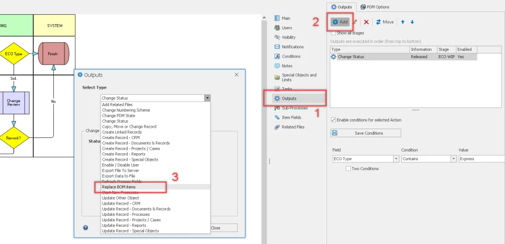
Each workflow stage can have multiple automated outputs, which can perform various actions such as creating new records, updating existing ones, changing PDM states, adding related files, exporting files, and more. The ‘Replace BOM Items’ output is one of these actions. It allows you to replace an item with another in the Bill of Materials of the affected process items. However, it only replaces manually added BOM items and does not affect items added through SOLIDWORKS, for example.
This process output requires the configuration of two Object Type fields within the process itself. If these fields have not yet been created, you’ll need to close the configuration page and set them up before proceeding.
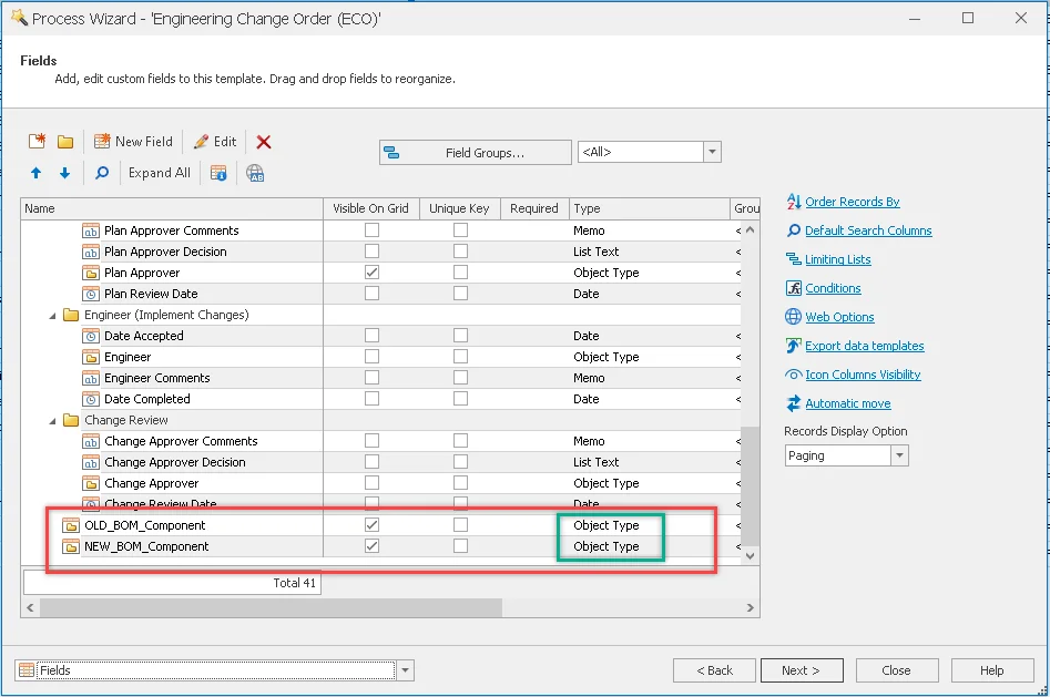
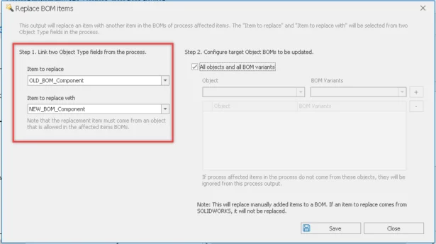
STEP 1. Link two Object Type fields from the process. Navigate to Workflow Properties > Choose the desired stage > Access the Outputs section > Set the type to Replace BOM items.
- Select Item to Replace from the Drop-Down List: This option will only display object type fields that are available within the current process.
- Select Item to Replace With from the Drop-Down List: This option will only display object type fields available within the current process.
STEP 2. Configure target object BOMs to be updated.
In this step, you will configure the BOMs that can be modified using this output.
- If you select the “All Objects and All BOM Variants” option, all BOMs will be updated. However, if the “Item to Replace With” is not permitted in a specific BOM, it will not be replaced, and the user will be notified of the reason.
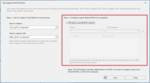
- If you deselect the “All Objects and All BOM Variants” option, you will be able to select specific objects and their corresponding BOM variants. This means that any process-affected items that do not originate from these specified target BOMs will be ignored.
- Finally, click Save and Close.
Once you’ve configured the fields and the ‘Replace Output BOM’ output, open the process record and add or select the corresponding values in the object type field.
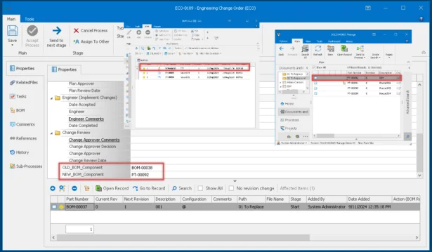
After saving the record, click the ‘Replace Analysis’ button as shown in the image. A pop-up window will appear, displaying the Record to Replace and the Record to Replace With.
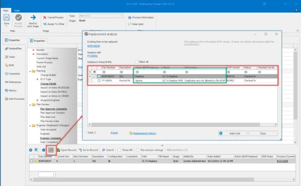
You can select records by checking the box next to each one. Click ‘Add to List’ to save your selections. Once this is completed, the records will be replaced at the end of the process stage where the ‘Replace Output BOM’ action is configured.
2. Working with Predefined Animation in SOLIDWORKS® Composer
By Prajakta LIMBASARKAR
Most of the SOLIDWORKS Composer users creates marketing, instructions videos, etc with Animations. If you often need to reuse the same animations across multiple projects or assemblies in SolidWorks Composer, the Animation Library is an invaluable resource.
The Animation Library simplifies the process of generating animations by providing a set of pre-defined, generic animation sequences, which can be easily applied to 3D actors.
You can find Animation library in Workshop tab. It consists of number of simple animations in each group of “Highlight” and “Motion”.
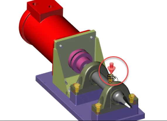
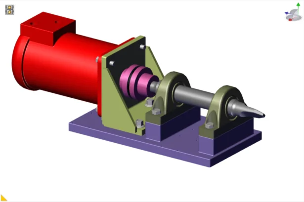
Let us create some predefine animations on the Overturning Mechanism assembly. We will create the animation of the fasteners unscrew from the assembly.
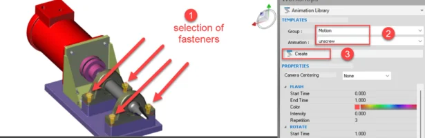
- We select the fasteners. Refer the below image.
- Go to Animation Library
- Select Motion in Group dropdown
- Select Unscrew in Animation dropdown
- Click Create
Unscrew animation is made of a sequence of Flash, Rotate and Translate animations.
As the name says ‘Flash’, Highlights, ‘Rotate’ Rotates and ‘Translate’ Translates the selected actors. Let’s go in detail of each sub animations. Each sub animation has its own Start and End time. This means, the sequence of animations is customizable.
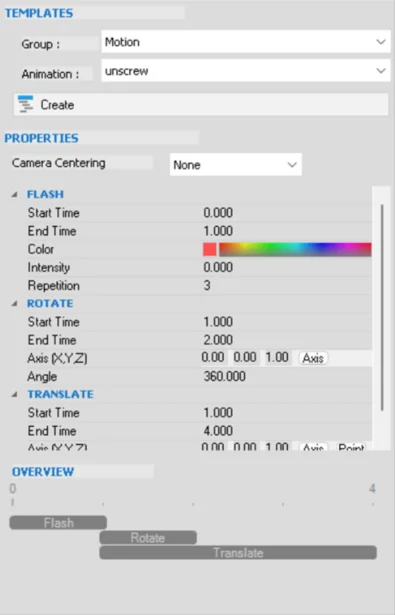
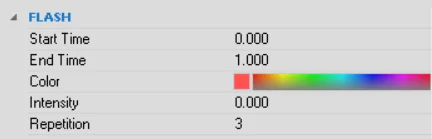
- For the Flash, we can define Color of highlight, Intensity of the emission and Highlight
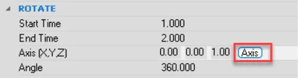
- Under Rotate, choose axis of rotation X, Y and Z. Enter value ‘1’ for the axis to make in use. Instead of choosing axis, we pick the axis of the actors. To do so click on Axis > press Alt to pick center of axis of the actor. Of course, for unscrewing we keep the default Angle of rotation 360.
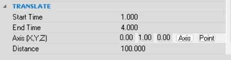
- For the Translate animation, we follow the same method to select axis for direction of translation as mentioned in Rotate animation. Also provided distance of translation.
- On every change in parameters the Overview gives a graphical overview of the order of motions in global animation. Once the we are satisfied with necessary changes, run the animation.
In the Timeline, check the animation block is created. This block can be expanded, collapsed and even move across the timeline. Animation blocks consists of multiple animation keys restricted to the respective blocks. This avoids the situation of overlapping of multiple animations with individual keys in the Timeline. You can also create multiple animation blocks and manipulate them together.
Now you try the animations from the library and write us in case of query.
3. Understanding the Dirty Mark (*) in SOLIDWORKS®
By Jayendra POTDAR
What is the Dirty Mark?
The asterisk (*) next to a file name in SOLIDWORKS indicates that changes have been made to the file but have not been saved yet. It serves as a reminder that the file needs to be saved to retain the changes.
Causes of the Dirty Mark appearing:
- Making geometric changes to a part or assembly: Modifying dimensions, adding features, or changing geometry within a part or assembly can trigger the Dirty Mark. These changes alter the model and require saving to preserve the modifications.
- Failing equations or mates: When equations or mates fail to resolve properly due to changes in geometry or configuration, SOLIDWORKS marks the file as dirty. This prompts users to review and correct these issues before saving.
- Changing system units: Adjusting units within a part or assembly affects dimensions and properties. Such changes trigger the Dirty Mark to indicate that adjustments have been made and need to be saved to maintain accuracy.
- Circular references: Circular references occur when entities refer to each other in a way that leads to an endless loop of dependency. With Circular references, a rebuild occurs and hence a Dirty Mark is triggered.
- Corrupt geometry or inconsistent face IDs: Issues like corrupt geometry or inconsistent face IDs can occur due to modeling errors or importing problems. These inconsistencies trigger the Dirty Mark, prompting users to address and rectify these issues to ensure model integrity.
- Incorrect appearance assignments: Assigning incorrect appearances or materials to faces or components can lead to discrepancies in the model’s visual representation. SOLIDWORKS flags these discrepancies with the Dirty Mark, indicating the need for correction and subsequent saving of changes.
Understanding these triggers helps SOLIDWORKS users effectively manage their design processes, ensuring that changes are properly tracked and saved to maintain the accuracy and integrity of their models.
Behavior Issues with Dirty Mark:
Sometimes, users report issues where the Dirty Mark doesn’t appear despite making changes in the session. This can be frustrating as it might lead to accidentally losing changes if not saved promptly.
Identifying Rebuild Conditions in Assemblies:
- To determine which features or conditions in an assembly require a rebuild, follow these steps:
- Open the assembly in SOLIDWORKS.
- Make changes as desired.
- Use File Explorer and look for files with bold highlights when you use Open in SOLIDWORKS from the Task Pane. Files in bold have been modified and may have a Dirty Mark.
- An assembly immediately displays a dirty mark when it is opened, and even though no changes have been done, SOLIDWORKS prompts us to save data when we try to dismiss the assembly:
- Sometimes, upon opening the assembly, the assembly displays a Dirty Mark (*) icon, as shown below:
- Rebuilding (Ctrl + Q) or force rebuilding (Ctrl + Shift + Q) in SOLIDWORKS initiates updates across the entire assembly.
- However, if there are certain external references are linked to the parent assembly, they get updated automatically each time the assembly is rebuilt.
- This update process triggers the Dirty Mark (*), indicating that changes have been made to the assembly.
- To remove the dirty mark, rebuild the parts or assemblies that contain external references.
- Sometimes, upon opening the assembly, the assembly displays a Dirty Mark (*) icon, as shown below:
To maintain the most recent modifications, it is always advised that the user saves the document before closing the session.
Addressing Issues with Dirty Mark:
If the Dirty Mark is not triggering correctly after making changes, it could be due to software bugs or configuration issues. Here are some steps to mitigate such problems:
- Upgrade SOLIDWORKS: Ensure you are using the latest version of SOLIDWORKS as updates often include bug fixes.
- Check File Properties: Verify that the files you are working with are not set to read-only or have permissions issues that prevent saving.
- Restart SOLIDWORKS: Sometimes, restarting the software can resolve transient issues with Dirty Marks not appearing.
- Report Issues: If problems persist, report them to the SOLIDWORKS Technical Support so they can investigate and provide a fix in future updates.
You can efficiently manage modifications and make sure your work is correctly saved and recorded in SOLIDWORKS by being aware of potential problems and comprehending how the Dirty Mark (*) functions.
Happy Designing!