

Welcome to Part 2 of this design and make project. If you’ve not seen or read part 1, I suggest you start here.
When we concluded Part 1, we had completed the design on our acrylic pressure pot, this section is going to show you how I brought the design to life. Step one was to choose a suitable material, I decided on aluminum for this. Aluminum offers a good strength to weight ratio while also being readily available at my local metal profilers. I started by creating some simple DXF’s of the top view of the parts and asked for these profiles to be quoted in 15mm aluminum to match the thickness on the SOLIDWORKS models. For the tapped holes I replaced these with 5mm holes to allow for machining back to the finished dimensions.

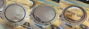
Once I had agreed to a quote for these to be cut, I went to work in creating some basic machining drawings. The machining needed on these is very basic. Essentially machine back to the correct OD, add some through or tapped holes, and create an internal pocket on the ring part. I had a local machining contact of mine do this work however I’m sure you could use the 3DEXPERIENCE Marketplace to find a willing contractor. After I’d dropped off the laser cut profiles and waited a week or so I collected the metal parts.
The acrylic tube was easy to source, and I ordered this from an online plastics supplier. The remaining arbitrary components such as O-Ring cord, thread rod and nuts were all picked up from a local hardware store.
Step one of the assembly process would be to check the machined O-ring grooves for any burrs or sharp edges which might have prevented a proper seal, the two small fillet radius’ we added during the design phase luckily make this pretty easy. By introducing this feature to the groove we’re increasing the sealing potential and forcing the machinist to use a ball nose or radius tool to create this. These sorts of tools pretty much eliminate any sharp edges or burrs. I cut the O-Ring cord to length, I didn’t measure this I simply laid it into the groove and eye-balled it however you can work it out if you want to be extra precise.
The next segment would be to install the upright thread rod to enable us to clamp together the upper ring and base. The length of thread rod I’d purchased was 1m, as I only needed this to be in 560mm sections I use a slitting disc on a handheld grinder to cut off the excess before installing a nyloc type nut onto one end. Once this was done for all 6 pieces, I inserted these through the bottom surface of the base piece before inserting the acrylic tube into the groove and placing the upper ring into position. I then used a small wrench to tighten the thread rod into position before torquing to 25Nm. I made up the 25Nm figure based on experience and similar pressures I’ve dealt with in my day job. I’m sure there’s a calculation you can do to turn the force on each endplate into torque and then divide this between the 6 connections, but I like to live dangerously.
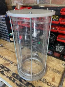
Once the acrylic tube was clamped between the base and ring pieces it was easy sailing to complete the build. I fitted some PTFE thread tape to the pressure gauge and push fit connector before screwing into the BSPP threads in the lid and securing. I then placed the lid onto the upper ring and secured using the wingnuts I’d modeled earlier. I’d used wingnuts because they’d be quick to install during the casting process but gave this some second thought and decided to use normal nyloc nuts which I could buzz into place quickly using an impact drill with a socket fitting. I made this change because I was worried that I’d struggle to meet the required clamping force to create a seal when using my fingers to tighten some rather flimsy looking wingnuts.
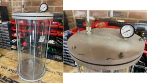
From this point the build was pretty much complete, I ran an air line from the manifold lock I have above my work bench to the inlet and installed a ¼ turn push fit valve to enable the pressure pot to be isolated when pressurized. I ran a pressure test on the system up to 70Psi, 10Psi above normal use to ensure all connections were sealed and no threads were leaking. On my first attempt I noticed a leak from the pressure gauge so gave this another half turn to seal the leak. A good technique to find leaks if your struggling is to use some soapy water and a small paint brush to paint this mixture around fittings. When the soap solution hits a leak, you’ll see a stream of small bubbles created highlighting the leak.
Thanks for reading this two-part project, I hope you’ve enjoyed it. Check out the making video below.