
If you read my Festive Ornaments blog last year, you’ll know how much of a pain casting clear epoxy can be, if you haven’t you can check it out here. In the blog I use some techniques that can help to release trapped air from within a casting but ultimately casting under positive pressure is the best way to prevent bubbles. It works by essentially applying so much pressure against the bubbles that they are forced to collapse and rise out of the parts. I ended that blog by saying I intended to build my own pressure casting tank and since then have been thinking about how best to do so.
I decided I wanted to move away from the traditional hard metal pressure tank design and set about working out the feasibility of creating a tank using clear acrylic tubing. The tube would need to be big enough to allow cast parts to fit within it but not too big where the tube would become a special ordered size or become too big to be usable within my workshop. I also wanted to be sure the acrylic tube selected would be strong enough to hold the pressure required to allow for clear castings. I completed the below simple internal pressure calculation to check that the thickness would be sufficient to hold the pressure safely. Barlow’s formula is shown below:
P = (2*T*S/D), where:
- S = allowable stress = 44.9-88.6Mpa / 6510-12500Psi
- T = wall thickness = 5mm / 0.2”
- D = outside diameter = 250mm / 10”
P = (2*0.2*6510 / 10) = 260.4Psi Bursting Pressure
When we apply a Factor of safety of 4, we arrive at a max allowable working pressure of 65.1Psi. During the calculation lowest yield stress value have been used therefore realistically the allowable pressure is likely higher than this, however, for resin casting we only need to achieve a pressure of 60Psig therefore the tube size and material is suitable for the design we are going to create.
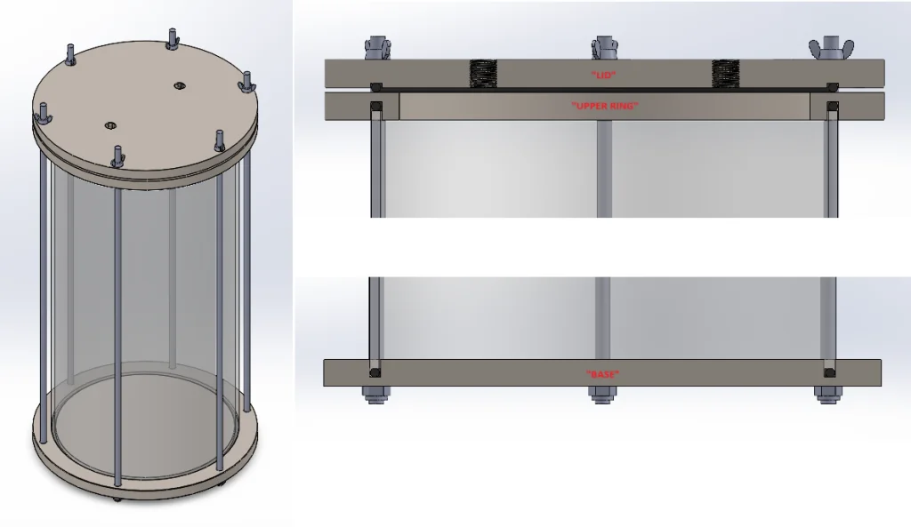
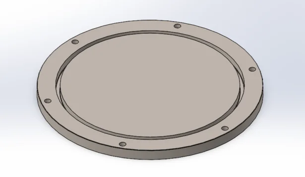
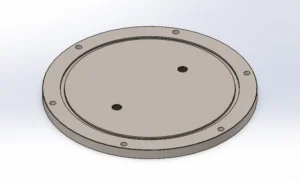
To start the design, I created a base piece which would have an O-ring groove for the tube to seal against, I sketched a round circle 300mm in diameter before extruding 15mm in height. Into this I cut a groove by creating a new sketch on the upper surface using two circles 6mm apart, the larger of the two would have a diameter of 250.5mm. I gave 0.5mm of space each side of the area the tube would take up to allow for any distortion in the casting of the tube. The O-ring I specified was 5mm in diameter therefore I cut the groove 10mm deep before adding a 0.25 radius fillet to the 2 lower edges. I knew I was going to use M8 thread rod to pull the assembly together so added 6x 8.5mm holes evenly space on a 280.75mm PCD. I did this by positioning one circle in a sketch before using the extrude cut command followed by the circular pattern tool to achieve the result.
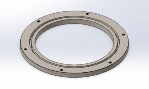
The upper ring was going to be similar in form to that of the base, however it would have a cutout to allow loading of parts into the chamber. I saved of the base part under a new name “Ring”. I rolled back the part until the single blind hole was present, I then used the thread tool to add an M8 thread to this hole to represent the area where the thread rod would secure to. Rolling forward the assembly I had to edit the circular pattern to include the additional thread feature as well as the previously created blind hole. To complete the part, I added the required cutout to the center by sketching a 220mm diameter circle and using the simple extrude cut command to remove the center portion of material from the design.
The final part of the assembly which would need to be machined would be the closure lid. Again, to keep this as simple as possibly this would seal against the upper ring using an O-ring type seal. The Part would be very similar to the base however the O-ring would be in a shallower groove to allow it to compress against the upper rings surface. The easiest way to achieve this was to open the base part and save this as a new part under the name “Lid”. From here it was a quick and simple process to edit the extruded cut which created the O-ring groove, I edited the cut depth from 10mm to 2.5mm. This depth would be sufficient to hold the O-ring in place but also shallow enough to allow it to compress and seal.
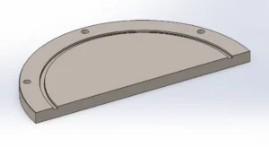
The final change which I needed to make to the lid was to add 2 threaded holes. One would be used to pressurize the assembly through and the other to allow a pressure gauge to be added to monitor the internal pressure. To create these features, I made a new sketch with two circles equally spaced either side of center. These were then cut blind through the material using the extruded cut command before using the thread tool to add a ¼” BSPP thread which would match that of the gauge and fittings I’d be using.
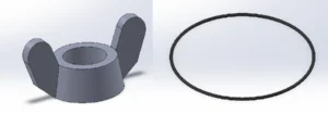
The next thing to do was to make a few remaining arbitrary components, the acrylic tube is a simple part made using two circles extruded the 500mm height of the tube sections I would be using. The thread rod I modeled as 8mm solid bar as threads can be heavy on GPU load, for the model I needed this would suffice in showing how the assembly would be held together. The wing nuts I modeled as representations and again left off the threaded portions. The O-ring was another simple component modeled using a circle offset from origin before revolving around a created line at origin to create the ring shape.
Once I had all the components, I started the assembly by adding the base piece and mating to the top plane. I then added the bottom O-ring, mating into position within the groove, upon this I added and mated the clear acrylic tube. I repeated this for the upper ring and lid before mating one nyloc type nut to the bottom of the base, into this I inserted and mated the thread rod before using a circular pattern to show 6 of these components equally spaced around the circumference. From there the final components to add was a wing nut which would be used to secure the lid into position and provide the clamping force to engage the O-ring.

This concluded the design phase of this project, check back soon on the SOLIDWORKS Tech Blog for Part 2 for the making of this project!