
My chess pieces were modeled entirely within the 3D sculptor app, xShape. xShape uses subdivision modeling, you start with a 3D shape primitive, and use push and pull techniques with a Robot to model. For this tutorial, I’ll show you how I modeled the pawn, rook, and knight chess pieces. xShape is a very freeform application, so our models won’t match up exactly, you can follow my tutorial as closely as you can, but you are also free to create your own designs. I’ll be focusing on the use of the crease tool, subdivision extrude and inserting loops.

Once the design window opens I can create some sketches as size guides for my chess piece, these will just be guides to design to so that I don’t have out of scale pieces and the set comes together more cohesively, Adding a guide sketch for the width/base diameter and overall height will make it easier to model within these boundaries.
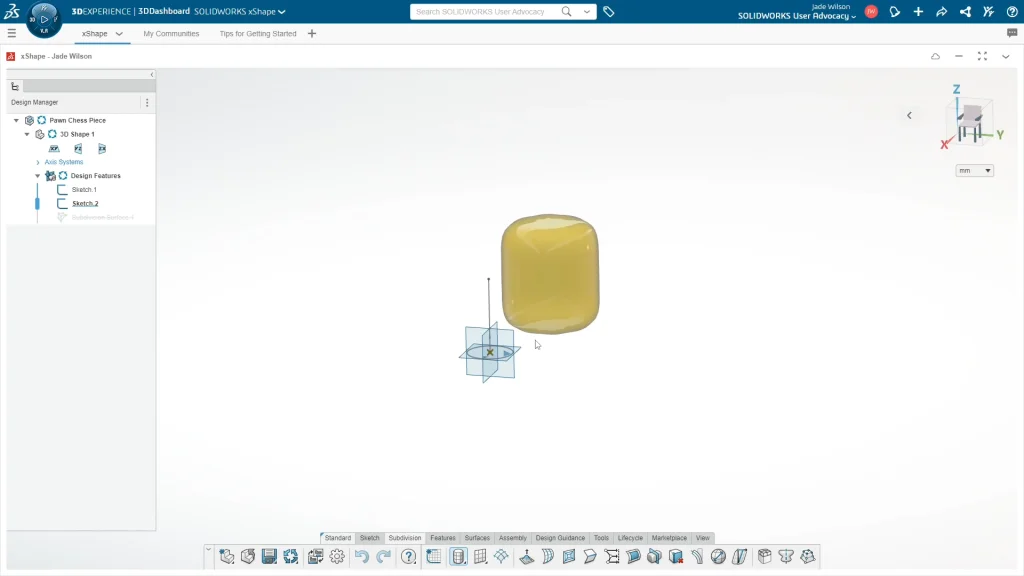
The next step is to choose a primitive to start modeling, you’ll find these shapes under the subdivision tab, use the drop down to see the shape options, I used the cylinder for all my pieces as I knew that this would be the easiest one to create my designs with. You’ll find that the more you use the app, the more you’ll instinctively know which shape is best to start your modeling with.
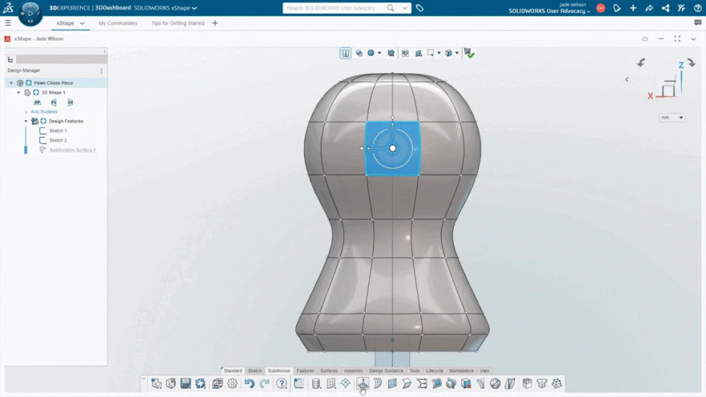
With the rough shape in place I can create the hole through the shape. I viewed my model from the side profile and selected a center face of the shape, I could then use the subdivision extrude feature, you’ll see in the gif below that initially the face extrudes out, but to create a hole through the shape, you need to select the face on the opposite side of the model, the preview will change to a hole, and I can apply it.
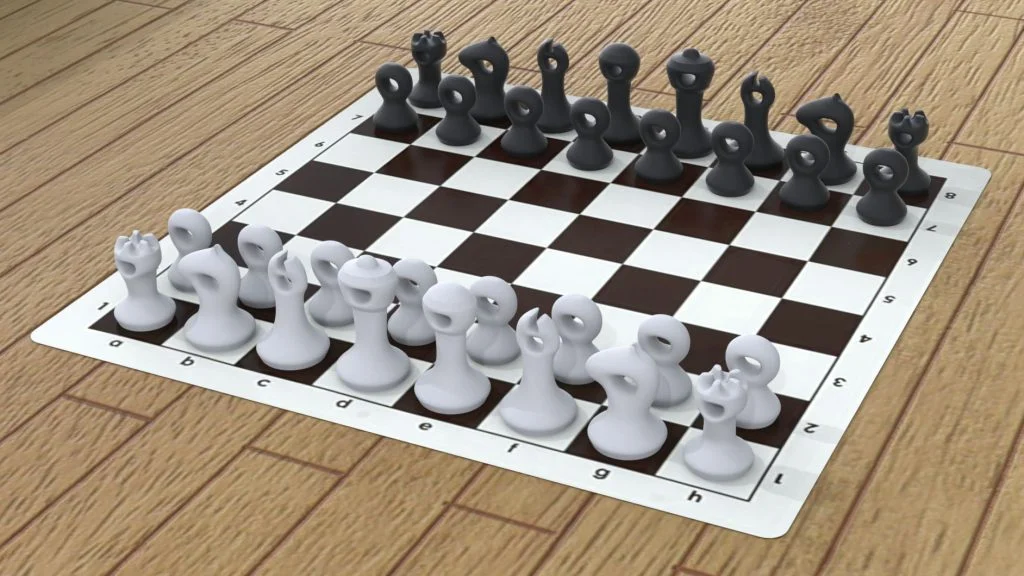
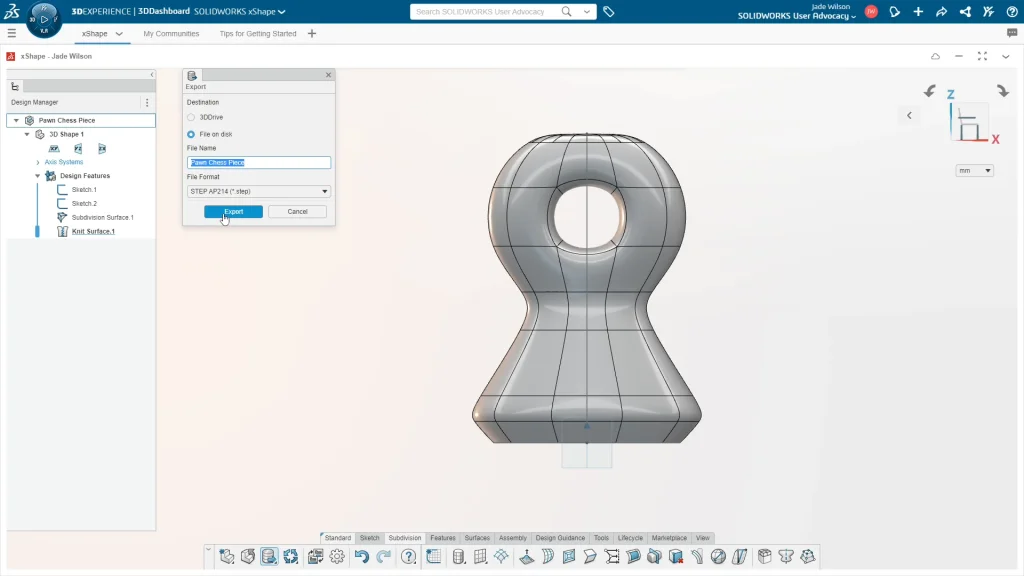
Once I’ve finished a design you can close the shape to knit it, or you can select save, the shape will close and knit itself into a solid body. I like to export my models using the export option under the save drop down to be able to bring the model into SOLIDWORKS. I can then use my models to create the animation and renders you’ll see in the tutorial. If you want to do this too, and you’re using your desktop version of SOLIDWORKS, just change the destination to file on disk and change the file type to STEP AP214, and save the file where you want it.
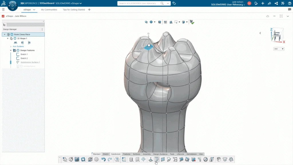
The extrude tool and the crease edges tool was used to create the turrets on the rook piece, the useful thing about the crease tool is the ability to have very straight edges, or completely rounded edges, and anywhere in between.
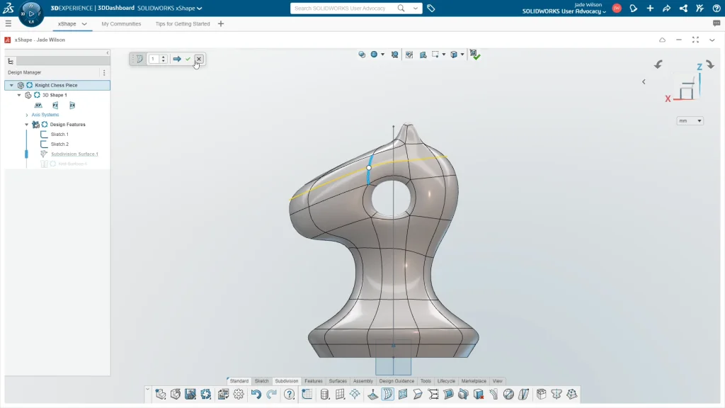
Insert loops can be used to add more control options to a shape, you can find this feature under the subdivision tab, when you select the insert loops icon, you select the edge that you want the loop to apply across and a preview of the loop will appear. Adding too many loops can make a model more difficult to work with, so you need to add them sparingly, when added wisely they can give you more control over your shape. If you have too many loops in a shape, you can always delete loops too.
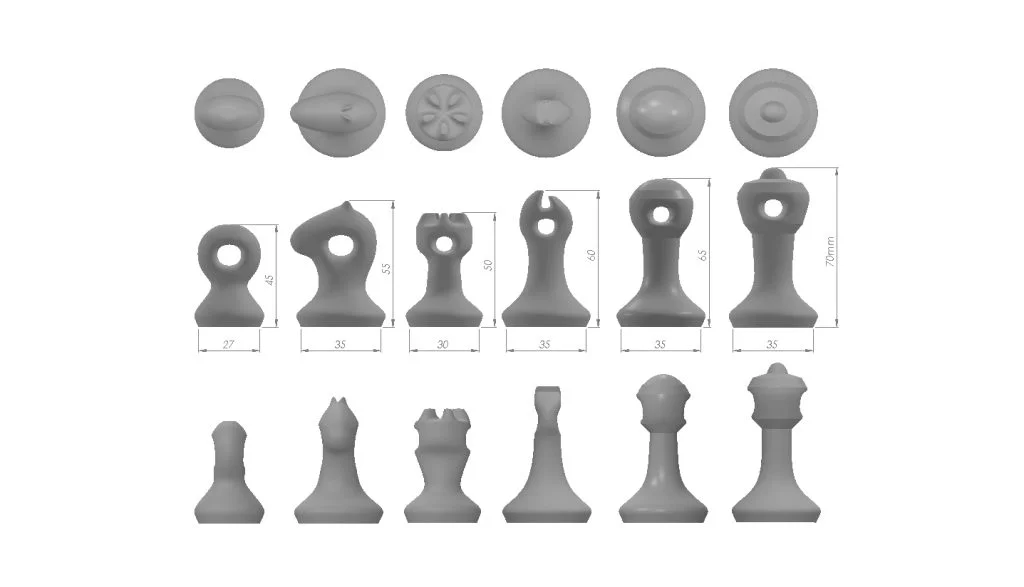
If you want to create the rest of the set, as I mentioned in the tutorial, its useful to use other models to create them. I used the pawn as a base to create all of the parts. The bishop, queen and king all have a guide base sketch of 35mm, and go up in height by 5mm each. So, the bishop is 60mm tall, the queen is 65mm, and the king is 70mm. You can see below there is a SOLIDWORKS drawing of the chess pieces to make it easier to recreate the other pieces. The exported models were brought into SOLIDWORKS to create an animation for rendering in SOLIDWORKS Visualize, which you can watch in the tutorial.