
When I’m designing for a client, I am usually given a brief to work towards, from the brief I like to create varied options within the brief guidelines to give the client choices, The choices can involve subtle changes within a parts dimensions or features, the quickest way to do this without creating multiple new parts is through configurations. In this tutorial I will show you how I created a set of global variables in preparation for designing the unit.
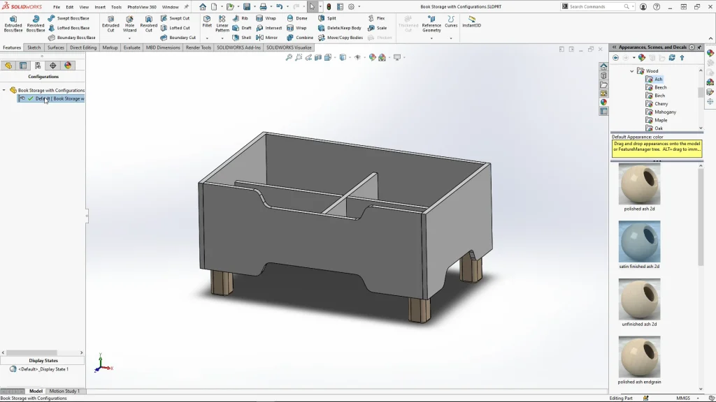
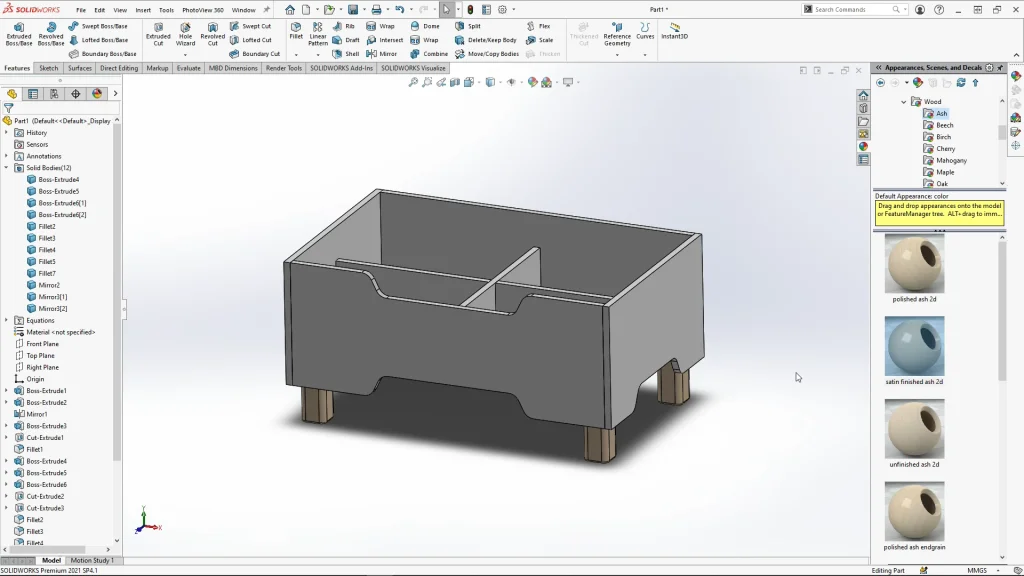
For the initial modelling of the multi-body part, I designed the book storage unit with all the features applied. The below image shows you how the model looked at this stage, it is not pretty! but I wanted to have all of my features in place ready to create some options using configurations. By designing this way, I could start creating configurations for each ‘design option’ I wanted to produce for in this case an imaginary client. From here I could then suppress features or edit the dimensions of features through manage equations.
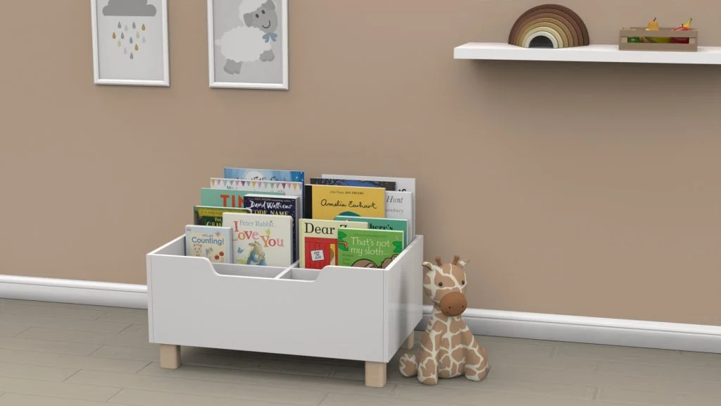
Looking at the below rendering created with SOLIDWORKS Visualize, you can see a cube option of the storage unit which I duplicated for the rendering. For this option I needed to suppress the storage divider extrusions using configure feature, I also needed to edit sketch dimensions which was much easier to do using manage equations and simply editing the previously added dimensions within global variables. When doing this you have the option to apply the edits to ‘All Configurations’, this includes being able to select ‘This Configuration’. This is such a useful feature as it allows me to make changes to the configuration, I’m working within without changing anything within other configurations.
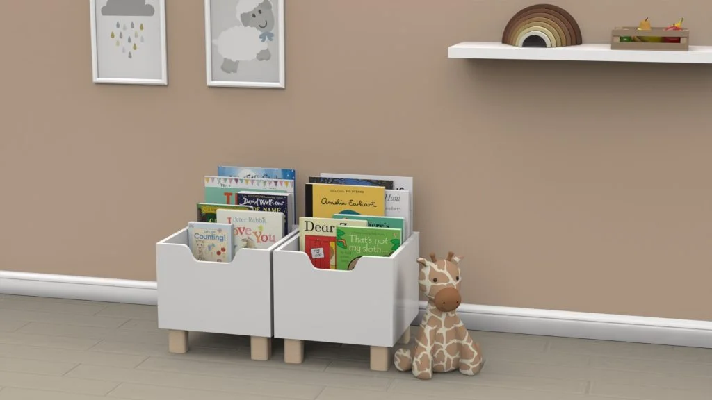
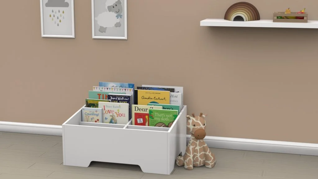
For this design I created 5 different configurations, this included adding legs and removing legs, adding and removing cut extrusions, and changing the sides of the unit from straight to angled (creating the angled sides did come with some issues, but I show you how I amend these within the tutorial) The rendering below shows one of my angled configurations which had the legs removed, and the floor level cut extrusions un suppressed to give you the illusion of feet within the panels which lift it off of the ground. A design option like this could save a client money by removing the chunky wooden legs and adding a built in ‘feet’ feature within the panels. The sides of this panel are also angled using a ‘front panel height’ global variable, angling the sides of the unit could help you see more of the books on display allowing me to suppress the top center cut away that I applied to the other two options.
The time I have saved for both myself, and clients when they have needed to see variations of a design concept is substantial, yes it does take some time to set up the equations for the model, but once these foundations are in place, you can create endless variations of your model. It makes those niggly design tweaks easy to do, without you needing to go back through all of your individual features and sketches to edit dimensions. Instead, it is all stored within the equations table, and all of my ‘design options’ are listed as configurations that I can easily switch between to view.