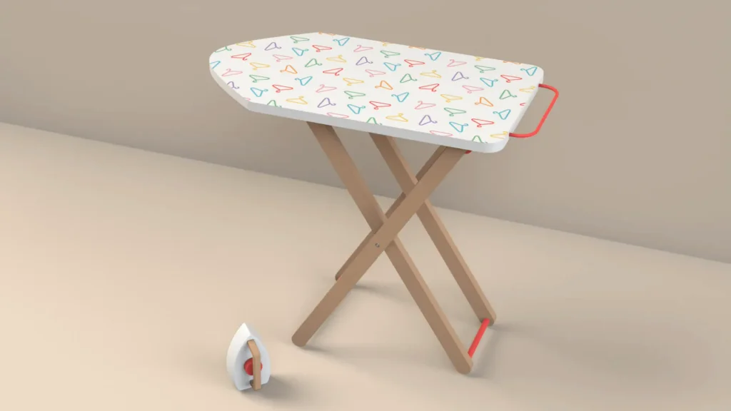

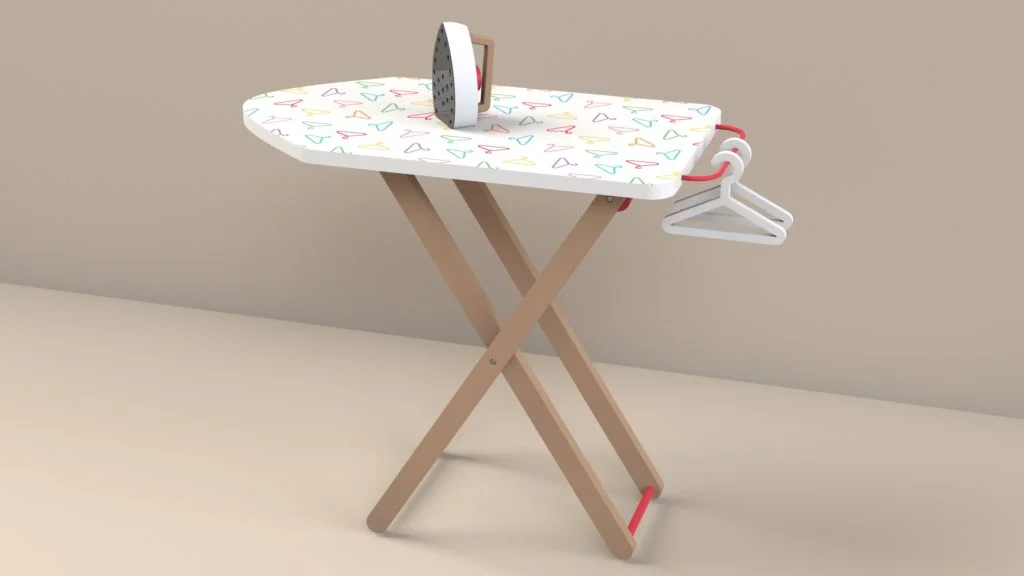
I have designed ironing boards in the past as a toy designer, and something I would have to test for is how the toy would open/close, and at what height it would be for a child to play with the toy. On occasion for toy buyers or even for the toy factories to use and refer to, I would need to create an animation to illustrate how a toy should work, this is useful to them, but also for myself to ensure the design works. The rendering below of the full assembled ironing board also includes some accessories, you can download the files for the tutorial assembly here
During the tutorial, I take you through the assembly of all the parts, I simplified the parts of the ironing board for the assembly by having main parts already connected, for example the inner legs are made up of two legs held together with two poles, I do this to simplify the assembly of a design, but also for motion study purposes, having fewer mated parts can speed up your calculations. It’s important to follow the mates I apply to the parts as they could affect how the parts can move, the legs are mated together with coincident and concentric mates at the screw holes, the concentric mates are left unlocked to turn freely, however when it comes to adding the custom screw fastenings, these need to be mated concentric with rotation locked. This again simplifies the motion study as the screw parts are fully defined within the moving parts, the legs can move on the screws, but the screws will not turn.
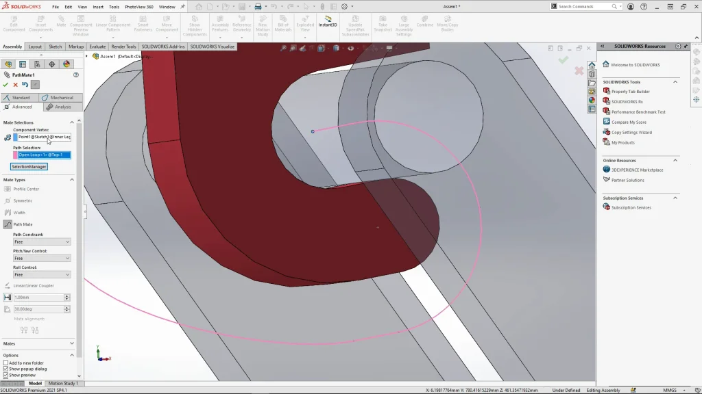
The most important mate needed for this model was the path mate, the path I have sketched out was created within the ironing board top part on its front plane. This was necessary to do as the part needs to move and if the sketch was added to the assembly instead, it just wouldn’t work. I used a mock assembly to work out were the path needed to be for the moving parts and then added it to the top part, this ensured that I had no collision between the legs and the top. Under advanced mates you can find the path mate, for this mate type you need a component vertex and the path sketch. The component vertex was added to the middle of the inner legs pole, this is the pole that slots into the hooks on the top ironing board part to change the height. This vertex will follow the path sketch, to select the path, I used the selection manager and used ‘open loop’ so that I select the whole path sketch. With the path selected, I leave all the path constraints free for the analysis and then apply the mate. The final mates I added were tangent mates to sit the ironing board onto the floor, the final mate placed the legs at the starting position of the path, this ensures that my analysis runs from the beginning of my path so that the ironing board is in the full upright position from the start of my analysis.
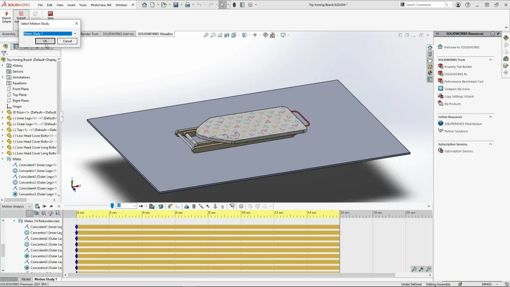
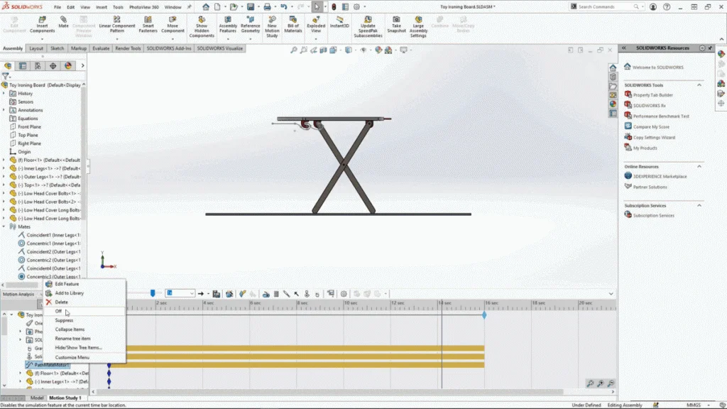
With all the mates applied, I could start the motion study, for this assembly I needed to use motion study, that was I could add gravity and contacts to the study. The coincident mate used to place the legs at the start position of the path mate was suppressed to allow the legs to move along the path once the path motor was added. The total length of my analysis was 16 seconds, I set the path mate motor to travel 420mm within 15 seconds, 420mm is just short of the overall length of the path sketch, so as it nears the end of the path, I need the motor to stop. To do this I drag the time bar up to 14.2 seconds, right click onto the path motor and turn off the path motor. By doing this, the motor will stop at this time point and gravity will take over to completely collapse the ironing board onto the floor. If the motor remained on, the ironing board would flip over due to the momentum.
Once the analysis has run you can play it back, if the model view changes when you try to view it from different directions you can disable the playback of view keys right clicking orientation and camera views. That way you can view the model freely as the study plays out. From this point I always resave my assembly, then using the SOLIDWORKS visualize tab I can select export advanced and select the motion study name that I am working within, this then exports the motion analysis animation data into SOLIDWORKS visualize to render the animation, you can see the result at the end of the tutorial.