

In this blog you will find tools to remove unwanted surfaces or a few direct editing tools. And to save your file into separated part files and assembly.
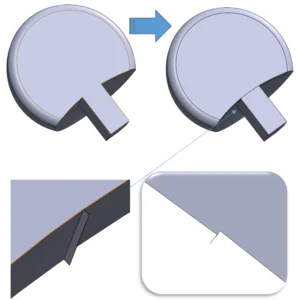
To remove this part, there are multiple ways, for example, use offset surface to copy the surface first:
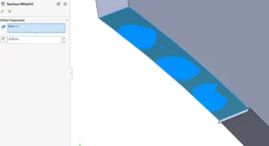
Noticing that the surface is the exact same size of the selected face, we have to extend it in order to “overlap” the bit of solid:
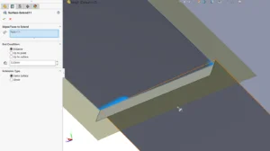
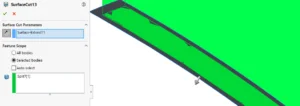
Finally, you could use surface cut to remove the excess solid part, pay attention to the cut direction and solid to be cut:
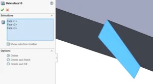
Or you could try a different approach, for example use delete face to remove the surfaces:
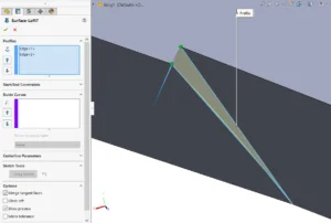
Create a loft surface from the two edges, so that you could trim and knit the surfaces to form solid again:
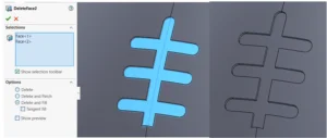
Speaking of delete face, there are two additional options “delete and patch” and “delete and fill”; both features are designed to remove selected faces and close up the void using the surrounding edges.
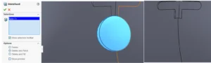
Using delete and patch, it allows you to remove selected face and fill it up by extending the surrounding faces:
And delete and fill allows you to remove selected face and fill it up based on the surrounding edges instead (tangency to face is optional)
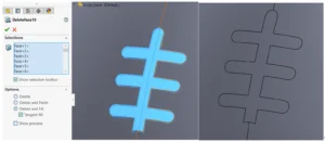
Delete and fill can basically fill any faces with continues edges:
As your part file is all tidied up, it is time to save the solid bodies to individual part files. Mainly there are two ways to do so:
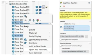
- Using insert into new part, you can save out one or more solid bodies into a new part file, to do this, simply right click the solid body/bodies you would like to save as a new part file:
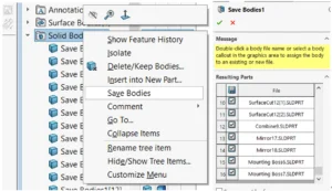
- If you want to save all solid bodies into separated part files, you could use “save bodies” instead by right-clicking the solid bodies folder, you could even create a new assembly at the same time:
Using both methods, it allows you to create a part file with link to the source part. If you wish to break the link to prevent update or change, right click the import feature to lock/break the external reference:
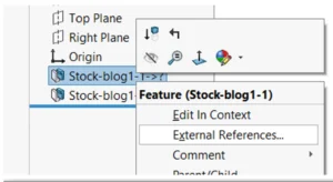
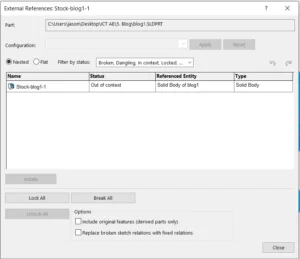
The following symbols display after the name of the part or feature:
–> External reference
-> * Locked external reference
-> x Broken external reference
-> ? Out-of-context external reference
{->} Feature contains a sketch with external references
This is the last part of the blog of “Answers to commonly asked surface and advanced modelling problems”. I believe we have gone through some of the major issues that you might face during model creation. If you have further questions or modelling difficulties, leave a question in the comment and we as SolidWorks community will gladly provide help. See you soon.
Written by Jason Tse, Intelligent CAD/CAM Technology Ltd.