

A Special Purpose Machine, which is intended to perform a specific task, have a wide range of scope in the Industrial Applications like quantity packaging and bottle filling. It includes limit switches, sensors, logic controls where the process can be automated and the production quantity can be increased.
Steps for Building an SPM machine
- Idea or concept
- Building the Design Using SOLIDWORKS
- Analyzing the model in SOLIDWORKS Simulation
- Prototyping & Testing
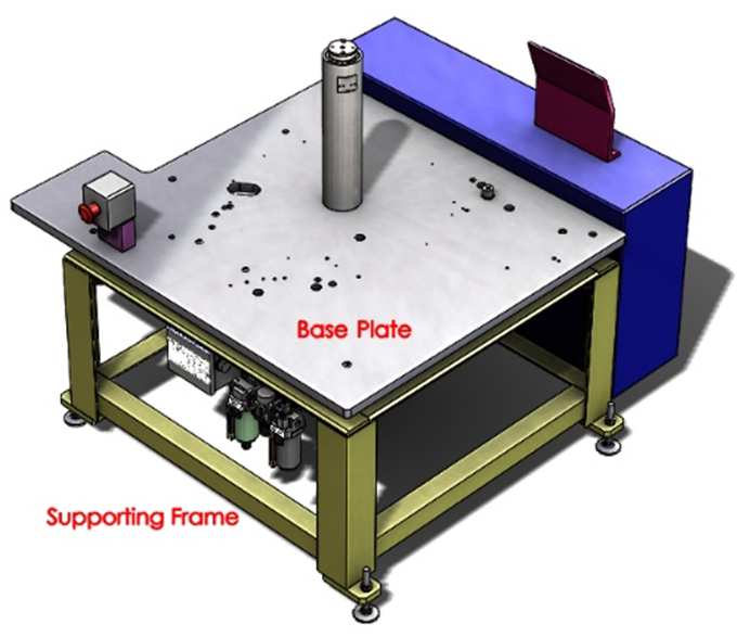
The analysis is done to get where the maximum stress is affected by the machine. When loads are applied, loadings such as vibration, self-weight of the machine are affected at the bolt and nut connections between the support frame and the machine. In SOLIDWORKS Simulation we can define the bolt connections directly to obtain the more accurate and realistic results in the bolted connection.
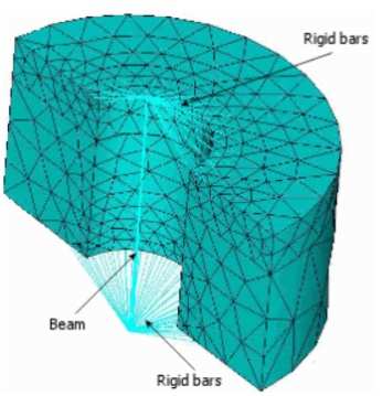
When a bolt connection is selected in the simulation, the software considers there is a straight beam element with axial and rotational degrees of freedom this represents the bolt shank, mechanical properties are defined by the material and diameter of the bolt. The rigid bar elements attached to the top represent the bolt head and the bottom represents nut as shown. This indicates that virtually the bottom face of the bolt head is connected to the top face of the component. Defined Frictional factor(K) is between the rigid bars and components.
Effect of Distributed Coupling on SPM
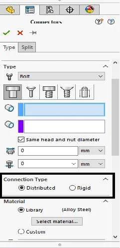
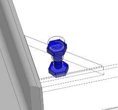
In the Connectors property there are two Connection Types, Distributed & Rigid as shown in Fig:1, when the distributed load is selected, the software assumes shank as beam element which has 2 nodes with 6 DOF, the First node is connected to the group of nodes of the region of the bolt head and in the same way Second is connected to the group region of the nut, by default distributed is selected. The rigid connection produces stress inside the region of the bolt. And nut on the connected components. Due to this there may be misleading of the results. Previously by default, the connection is considered rigid. When a bolted connection is given to the base plate and supporting frame. Then virtually the bolt and nut will appear as shown in Fig:2.
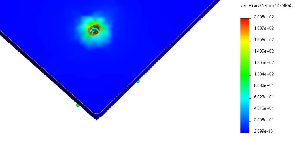
After running the analysis to check the stress results for the bolted connection between the base plate and the supporting frame for the distributed load are shown. With max stress of 200MPa which is in red is shown at the circumference of the hole.
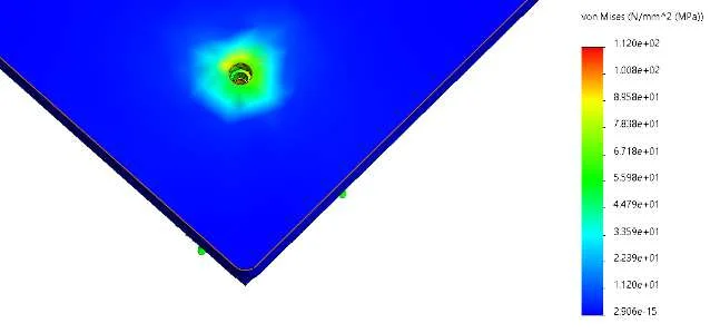
For The rigid type, stress results are shown in the Fig:2, the max stress is 112mPa. But the stress around the hole is in the range of 44MPa to 100 MPa where the value is misleading. Due to this, there will be a chance of failure of the bolt at an early stage.
In the actual scenario due to bolt preload, the bolt and nut will affect the contact surface of the component as shown in the distributed connection.