
Do you enjoy making home improvements? Do you have a flare for design and have some SOLIDWORKS skills?
Perhaps, you just want to install a fence? Depending on when and where you purchased your home it may have a fence already installed. Depending on the city or the Home Owners Association (HOA), there may be regulations governing the parameters of the fence, style, height, materials and color. It can be a challenge moving and relocating your fence.
In this blog, I will show you how to use SOLIDWORKS to create a Site Plan and submit to the HOA for approval. Some cities may require a building permit before you can begin construction. The Site Plan is how you can communicate the desired changes to your home.
I will show two separate Site Plans (A & B) that were created at different times, one year apart.
Site Plan A
The Site Plan should reflect the current state and the proposed or future state. Typically, it will have a north arrow as well as a title block. However, since this is not for an Architectural or Civil engineering firm these details were not necessary.
Site Plan A
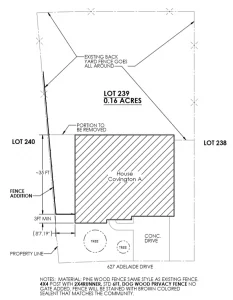
The first thing you must identify is the property line. This is provided when you purchase the home, or it may be on file at the city.
Site Plan A is needed for the left side of the home. The existing fence terminated at the rear left corner of the home. I wanted to move this fence forward to enclose the left side of the property line. The fence had to terminate at a specified distance from the front of the home. The specified distance was at least 3 feet or more set back from the front of the home. Once this was determined, I was able to begin my site plan.
I did not want to submit some hand sketch to the HOA. I wanted to present a professional drawing to increase my chances for approval and to ensure there was no misunderstanding. This is where SOLIDWORKS 3D CAD came to the rescue. Typically, SOLIDWORKS is used for Mechanical design and not for Architectural or Civil design, but that was not going to stop me. SOLIDWORKS had the tools I needed to bring my ideas to life!
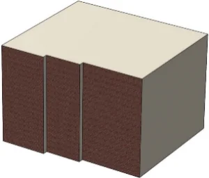
The first Feature used was the Boss Extrude command. This command was easy to use, and all I had to do was measure the house and create a sketch of the perimeter on the Top Reference Plane and extrude up to the desired height.
Then, I created a SOLIDWORKS drawing and added the 2D sketch entities using basic sketching tools. You can use blocks and other sketching techniques to layout the Site Plan.

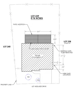
The Site Plan should include:
- Adjacent lots
- Existing trees
- Drive and walk ways
- Property line
- Fence addition
- Portion to be removed
- Any additional notes to identify, style, materials, color, and height
Site Plan B
Site Plan B affected the right side of the home to enclose all my utilities such as phone lines, cable, natural gas, and both air conditioning systems. All of these items need protecting. This was necessary because anyone could just walk up to the home and cut the phone lines disabling the alarm system from reaching the monitoring company. The fence also protects the AC units from being removed off their slab’s. I previously installed a Generac generator for those unexpected power outages.
Site Plan B
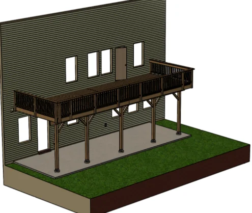
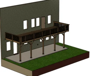
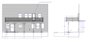
I also designed a patio with SOLIDWORKS and added this to the site plan as well. Due to the size, risk, and liability, I paid an architectural firm to review my plans and provide me with an approved set of drawings complete with this Architect Seal. They made one small modification to my design and then I hired a contractor to build it.

As you can see, the site plan took very little time and effort. All proposals were approved and built with ease (all images shown were created with SOLIDWORKS). SOLIDWORKS also has some amazing rendering capabilities as shown here:
You too may need to relocate your fence, add a patio, design a deck, build a retaining wall or even a swimming pool. Just remember, some elaborate additions will require the stamp of approval by a licensed architect (liability concerns).
Stay tuned for more home projects you to can create with SOLIDWORKS 3D CAD. With SOLIDWORKS, you are only limited by your imagination!
Warren McCray, Technical Solutions Consultant, TPM, Inc.