
If you’ve ever run into the case where you get the following message, seen below in Image 1: “At least two bodies are interfering. Do you want to check interference?”
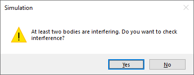
Image 1: Detected bodies that are interfering. Agghhh!
And I’m pretty sure that you have, so as you know it can be really frustrating. So you click to view the interfering bodies, such as in Image 2 below, and now in this case you wish that you could simply hit the “Ignore” button and for it to all go away. Well, read on if you want to find out how to fix this situation in SOLIDWORKS Simulation without having to modify the geometry.
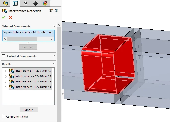
Image 2: Viewing interferences.
The problem isn’t really with the geometry, but with the default Global Contact condition set to Bonded. Typically the model geometry presented for a simulation is not be purpose-built for FEA but designed for another purpose, such as manufacturing. (I contend that SOLIDWORKS is the best pre-processor for FEA out on the market. A blog post maybe for another time.) To understand why the Global Bonded contact is the culprit in this case, you have to know a little bit more about the meshing process behind the scenes inside the software.
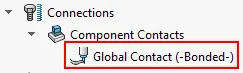
Image 3: Bonded global contact is the culprit.
In brief, the meshing process starts first by evaluating and meshing each surface of a body separately. It’s interesting to note here that for a Shell mesh type, the meshing process stops here but not for a Solid mesh. In the next step of a Solid mesh, it knits all the surfaces together at the nodes that are overlapping from adjacent surfaces to create a water-tight solid and then a different volume-filling mesher fills it in. When the Global Contact is defined as Bonded, then the meshing process will search for nodes from adjacent bodies now and try to collapse nodes that are close enough within the tolerance that you defined (or by default) in the mesh settings. When the faces are just touching, this scenario is desired, but when bodies are interfering, you could collapse two nodes that shouldn’t be and it can create some gnarly looking elements (with bad shape functions) that you don’t want to put into a finite-element solver. So SOLIDWORKS Simulation uses the Interference Detection tool on the CAD side of the house as a way to help prevent you from creating bad meshes. So this is a good thing! But I haven’t yet shown you how work around this geometry, ahem, meshing issue. The fix is actually quite easy.
What is needed is to change the Global Component Contact setting to either Allow Penetration or No Penetration, as in the image 4 below. I think that you could also just delete the Component Contact from the tree altogether, essentially making it to “allow penetration” or also known as free.
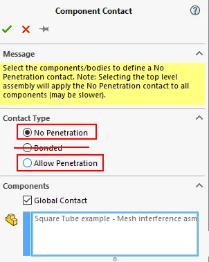
Image 4: Redefine the Global Component Contact type.
In either case, you will now need to define Local Contact sets in order to define how the bodies are interacting with one another. I recommend, when possible, to use the option to Automatically find contact sets, as shown in Image 5 below, even within gap tolerances if the faces are not touching. You can select the bodies to find pairs of faces that fit the criteria in the options; note that can also make quick work of this by window selecting all bodies and/or components. Then after finding the sets, you can click on each pair of faces that the automatic detection finds to visualize the faces in the graphics window. Shift+select all or Ctrl+select individual sets with the Type of contact that you want to define and then click the green Add button to add them to your simulation tree. Once added, the set is removed from the list so that you can define others differently, if needed.
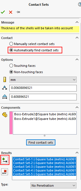
Image 5: Defining Local Contact sets automagically.
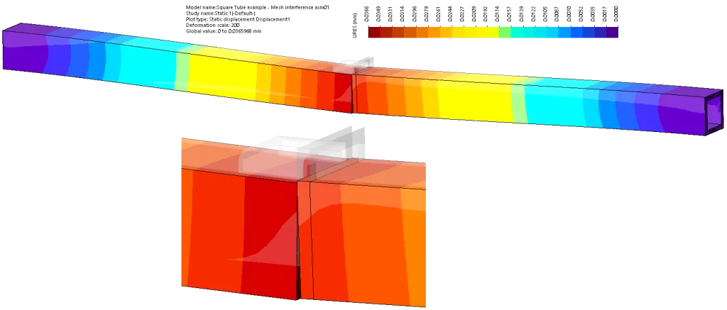
So in the end, (a) you don’t get bothered with a message telling you that bodies are interfering; (b) the model meshes successfully; and (c) you are able to get good valid results with the interaction between the parts that you would expect. Now in the example model that I am making available to download from here, I used the No Penetration contact types between the parts. I encourage to try this model out yourself but instead define the parts to be Bonded together. Start by copying the existing study to a new study and delete the local contact sets. When you do, make sure to check the Global Component contact is set correctly.

Image 6: Finished resultant displacements on an example model which originally had interferences between the parts. The image is a composite image (not directly from the software) to show more detail in the deformed joint at the bottom view.