
In this post I will continue with the building of my W16 engine by introducing the piston rings, the connecting rod parts and assembly, and finally, the whole assembly with the proper movement restricting mates.

See detailed explanation in the extended entry at the end of the post.
Thank you for reading about this build and stay tuned for the next post which will include the engine block and the math behind it.
George Bucsan
Worcester Polytechnic Institute
Aerospace Engineering, 2014
The first part of the assembly, the piston, is already made; therefore I will continue with the build of the others. There are three grooves for the rings. Two of the rings are identical (at least in our “simplified” model). I created them with a revolved feature starting from a rectangular sketch on the front plane. For the axis I used the easy approach, drawing a centerline in the same sketch as the profile.
The third ring, although overall having the same size as the previous ones, has to allow oil to flow from the holes in the piston to the cylinder. For this, I first made two thinner rings within the same part using the method stated above. Then, selecting the top face of the bottom ring, I sketched a line and extruded it using a thin feature up to the bottom surface of the top ring. I created an axis at the intersection of the front and right plane, and used it to make a circular pattern with the extrude joining the two small rings.
The next part of the assembly is the pin connecting the rod and the piston. It is created from a circle and an extrusion. Its length is equal to the distance between the two parallel plane surfaces cut onto the sides of the piston. By sketching two concentric circles instead of just one, I created a hollow pin.
An important part of this assembly is the connecting rod. It is built as a sub assembly of two parts and two bolts. To facilitate the building of the two parts that fit together perfectly I started with a single sketch, duplicated the file, and then continued with extrusions and other features. The basic sketch needs to have a circle that corresponds to the offset axle on the crankshaft and a circle that corresponds to the pin in the piston. I added a contour that encloses these two circles and looks similar to the profile in the reference file (it is easier to see that in the file). As a general tip, I used smart dimension for the distance between the centers of the circles, as it represents a very important dimension in the engine and needs to be easily changeable throughout the build, if needed.
After duplicating the sketch’s file, I drew a line in the place where the two parts should join and then trimmed the unneeded sketch items on each file. I extruded both sketches to the same thickness. Then, I created a ¼ inch clearance hole in the top face of the bottom part and, replicating the location of the hole on the bottom face of the top part, I created the corresponding ¼-20 tapped hole. Finally, I mirrored both holes about the right plane in each part.
From this point, the builds are separate. For the bottom part there is no other element, therefore I will continue with the top part. As it can be seen in the reference file, the upper conrod has a trapezoidal profile at the top. I recreated that profile on the right plane and then extruded it in a cut through all in both directions. To save weight, the part does not have a constant thickness; it has a so-called “H” profile. For that I created a profile that would fit onto the front face and would leave some thickness for the parallel lines of the “H”. I then extrude cut it into the part on both sides. For cosmetic purposes I applied fillets on the extrusion edges.
Using the two halves I created the “rod” assembly. The bottom surface of the top part is mated to the top surface of the bottom part (coincident mate), then the centers of the holes are mated correspondingly. Although now the parts are rigidly mated together, the real assembly also needs two screws to lock them together. I inserted two ¼-20 screws from the Design Library and saved them as a separate part. They are mated to the bottom surface of the lower conrond and to the axes of the holes, all coincidently.
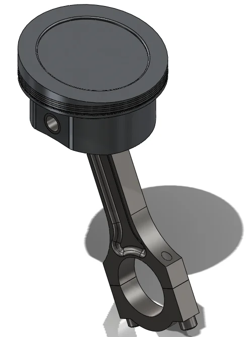
Now that I have all the elements needed, I can create the final assembly file and add them in. The first element is the piston; it will therefore be fixed. To make viewing orientations easier to work with, I floated the part, mated its origin to the assembly’s origin, and fixed it again. The second element is the pin. I mated its outside surface to the surface of the hole through the piston, and one of the end surfaces to one of the surfaces cut into the side of the piston. The third element is the conrod. The top hole is mated to the pin via its surface.
The interesting mates in this assembly are the advanced mates. The conrod can move left and right, but just enough to touch the inside of the piston. This is achieved through a limit distance mate between a flat surface inside the piston and the closest rod-extrude surface available (they have to be parallel; it becomes self-explanatory when you open the assembly). The parameters are: minimum distance = zero and maximum distance = distance between the parallel surfaces inside the piston “-“ thickness of the conrod extrude. The next mate limits the movement between the right plane of the assembly and the right plane of the conrod (now the origin mating above makes sense) by controlling the angle; I set it to (-42°, +42°). It is difficult to get this very precise, but if you look at the assembly in the front view with a wireframe display style and move the conrod either left or right, you can take an educated guess as to when it would touch the piston. You can also check your guess by doing interference/collision detection.
Thank you for reading about this build and stay tuned for the next post which will include the engine block and the math behind it.
George Bucsan
Worcester Polytechnic Institute
Aerospace Engineering, 2014