
After teaching 1000’s of students and writing about SOLIDWORKS and SOLIDWORKS Simulation, David Planchard, retired professor WPI, is exploring Design Study, Optimization Analysis and Generative Design. Through this lesson series, David helps educators and their students understand iterative processes through simple examples and industry practices.
This is a series of lessons to explore the meaning of Generative Design in SOLIDWORKS.
How do you perform an Optimization Analysis in SOLIDWORKS? How does the Optimization Analysis relate to a Design study? What types of design iterations should or can be performed?
In Lesson 1 & Lesson 2 we created a Design Study using various parameters (dimensions), constraints (von Mises stress and Factor of Safety) and set the goal to minimize the mass of the bracket, keeping the outer dimensions constant, while ensuring structural integrity.
In Lesson 3, we will explore Topology Optimization. Topology Optimization is more of a Simulation driven design tool. Topology Optimization is not limited to existing features and dimensions.
Topology Optimization is a technique to remove material from a user defined shape or design space to maximize the performance of the space. Optimization for Mass, Stiffness, Stress, Displacement and Frequency constraints can be targeted.
Topology Optimization allows students, designers and engineers to create efficient, lightweight, and structurally sound designs by determining the optimal material layout within a given design space. They can export optimized non-parametric shapes as a Graphics body, Solid body, or a Surface body.
My FSAE team found this particularly useful for end use parts where weight reduction and performance were critical considerations in an Additive Manufacturing process. A key approach to using Topology Optimization is to use a chunkier (more mass) model, to take advantage of the additional load paths to optimize the Topology Study for weight and stiffness.
In this lesson, open an existing SOLIDWORKS part. Create a Topology Study. Define the optimization problem. The Goal, obtain the best stiffness to weight ratio (default) for the bracket. The Constraint, reduce mass by 70 percent. Address two Manufacturing Controls: Preserved Region and Specify Symmetry Plane(s). Address Mesh Control. Create a Material Mass plot. Explore a few extraction techniques. Open the Solid body in SOLIDWORKS. Open the Mesh Model in SOLIDWORKS.
The Topology Study lesson provides a foundation to users who are new to using simulation to solve real-word engineering and design problems. A Solid body is used. SOLIDWORKS Simulation Premium is included in the SOLIDWORKS Education Edition. You should have a basic understanding of Stress and the Finite Element Method (FEM).
Start a SOLIDWORKS session from your desktop.
Double-click the SOLIDWORKS 2025 icon. The Welcome – SOLIDWORKS dialog box is displayed.
Close the Welcome dialog box.
Download and Open Cantilever_Bracket Part
Download the SOLIDWORKS Cantilever_Bracket part to follow along with this lesson.
Open the SOLIDWORKS Cantilever_Bracket part.
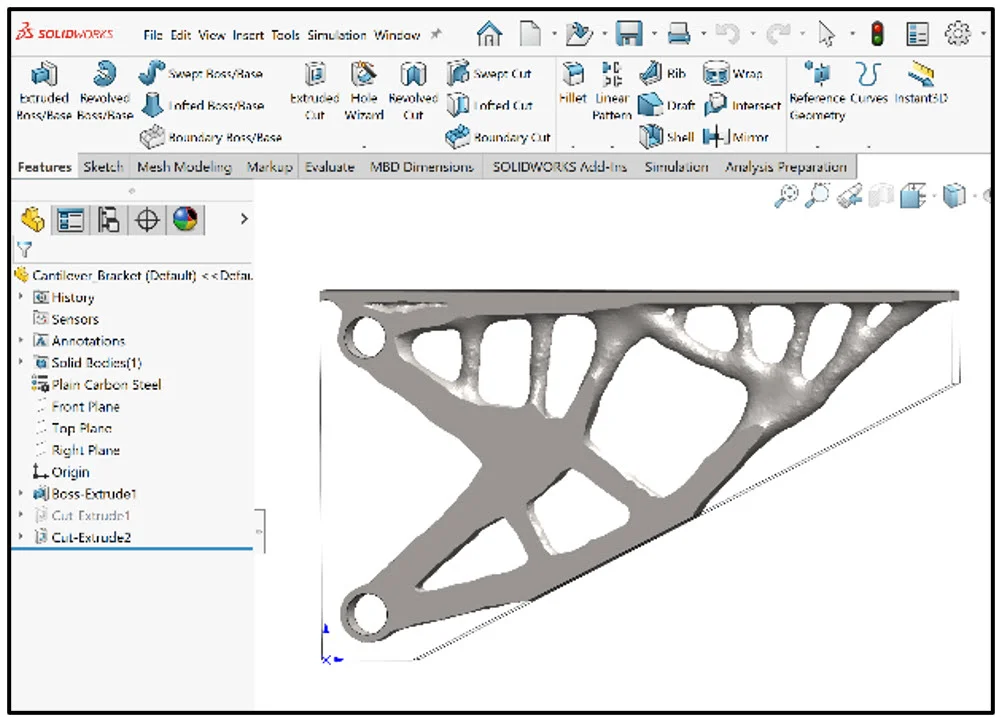
View the Part FeatureManager.
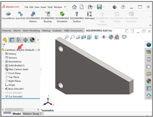
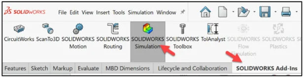
Click SOLIDWORKS Add-Ins from the CommandManager.
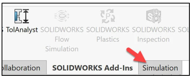
Click SOLIDWORKS Simulation.
Create a Topology Study in SOLIDWORKS Simulation
Click the Simulation tab.
Click the New Study icon.
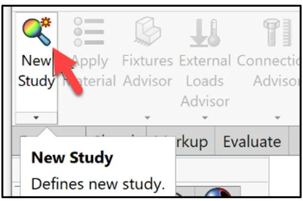
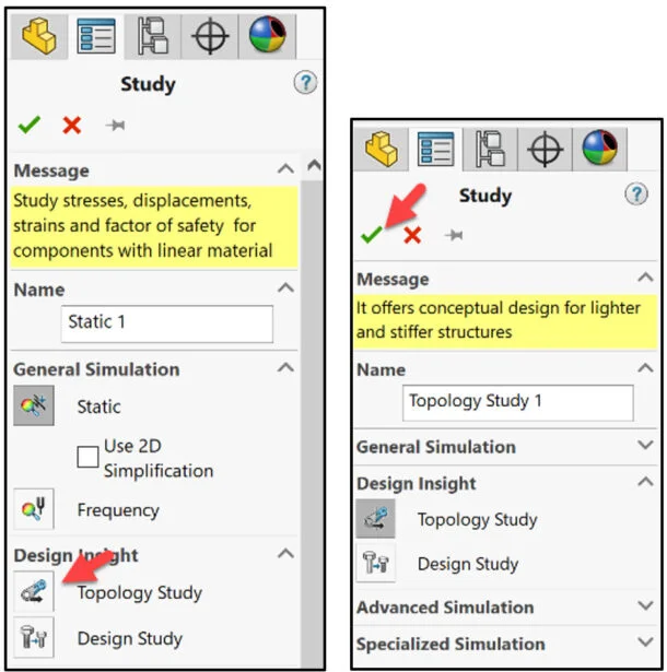
The Study PropertyManager is displayed.
Create a Topology Study. Note: A Topology study uses the same Fixtures, Loads, and Mesh settings as a Linear Static study.
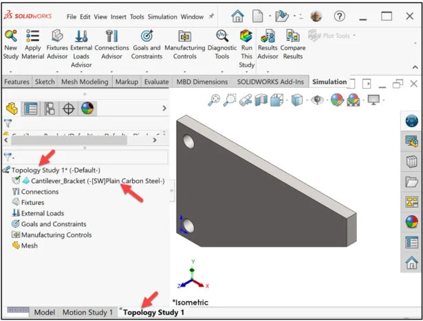
Select Topology Study for Design Insight Type. Accept the default name.
Click OK from the Study PropertyManager.
Topology Study 1 is displayed. Material is Plain Carbon Steel defined from the Cantilever_Bracket model in SOLIDWORKS. In an Additive Manufacturing process, we can address this with the 3D Printer type, Fused Filament Fabrication (FFF), STereoLithography (SLA), and Selective Laser Sintering (SLS), material type, setup, and a lab experiment.
Apply a Fixture to the model. The bracket is supported by two rods mounted through the two circular holes.
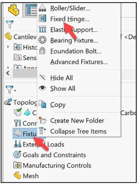
Right-click the Fixtures folder. View the Pop-up menu options.
Click Fixed Hinge.
The Fixture PropertyManager is displayed.
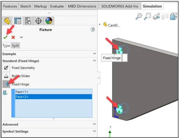
Click Fixed Hinge for Standard. The Hinge restraint specifies that a cylindrical face can only rotate about its own axis. The radius and the length of the cylindrical face remains constant under loading.
Select the inside face of the two holes as illustrated. Face<1> and Face <2> are displayed in the selection box.
Click OK from the Fixture PropertyManager.
Fixed Hinge-1 is displayed in the study.
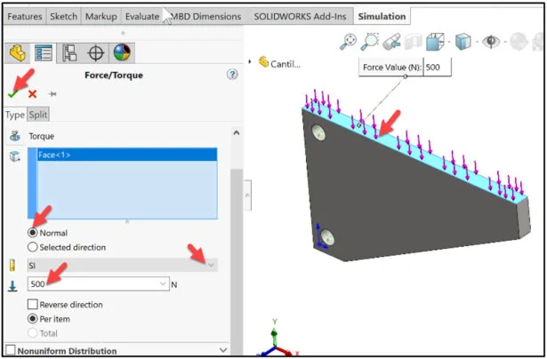
Apply an External Load (Force). The Force/Torque PropertyManager applies forces, moments, or torques with uniform distribution to faces, edges, reference points, vertices and beams in any direction for use in structural studies.
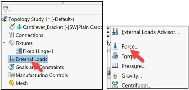
Right-click the External Loads folder in the study.
Click Force from the Pop-up menu. The Force/Torque PropertyManager is displayed.
Select the top face of the beam as illustrated. Face<1> is displayed in the selection box.
Click Normal. Enter 500N for Force.
Click OK from the Force/Torque PropertyManager. Force-1 is displayed in the study.
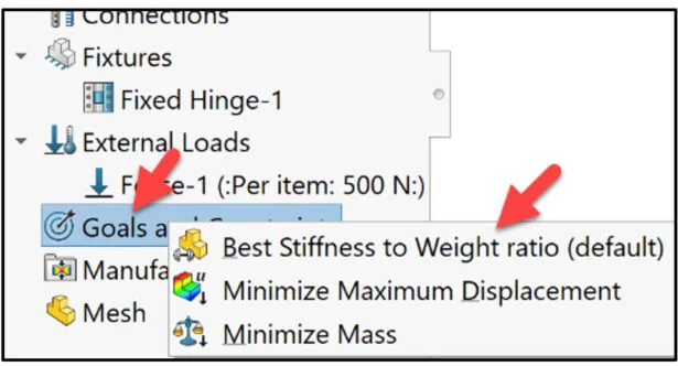
Define the optimization problem. There are three main Goals:
Best Stiffness to Weight ratio (default). The optimization algorithm yields the shape of a component with the largest stiffness considering the given amount of mass that will be removed from the initial maximum design space.
Minimize Maximum Displacement. The optimization algorithm yields a shape that minimizes the maximum displacement on a single node (calculated from a static study). With a given percentage of material to remove from a component, optimization yields the stiffest design that weighs less than the initial design and minimizes the maximum observed displacement.
Minimize Mass. The optimization algorithm yields a shape that weighs less than the maximum size model and does not violate the given target for the displacement constraint. The algorithm seeks to reduce the mass of a component while restricting the displacement (max observed value of component or user-defined at a single node) under a certain limit.
In this Lesson, we will design for an Additive Manufacturing process. Due to the unknown printer material properties, we will select the Goal – Best stiffness to weight ratio (default). Remember, it’s all about performing design iterations and deciding what is optimum for the application.
Right-click Goals and Constraints from the Topology Study.
Click Best Stiffness to Weight ratio (default).
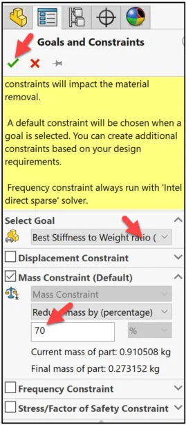
The Goals and Constraints PropertyManager is displayed.
Constraints limit the design space solutions by enforcing limits on the amount of mass that can be reduced and performance targets for the optimized model. The User Interface filters the type of constraints you can apply based on the optimization goal you select.
There are four Constraints:
Displacement. Specify the targeted mass that the part will be reduced by during optimization.
Mass. Specify the upper limit for the selected displacement component.
Frequency. Add the number of node shapes to enforce a frequency constraint during optimization.
Stress/Factor of Safety. Select Specified value to enter the maximum permissible von Mises stress for the optimized geometry. Select Specified percentage to enter the maximum permissible von Mises stress as a percentage of the material’s yield strength. Enter a minimum factor of safety value for the optimized geometry. The default failure criterion is the Maximum von Mises stress.
Enter 70 for Reduce mass by (percentage). Note: We can always go back and modify the Constraints values.
Click OK from the Goals and Constraints PropertyManager.
Topology Study 1* is displayed.
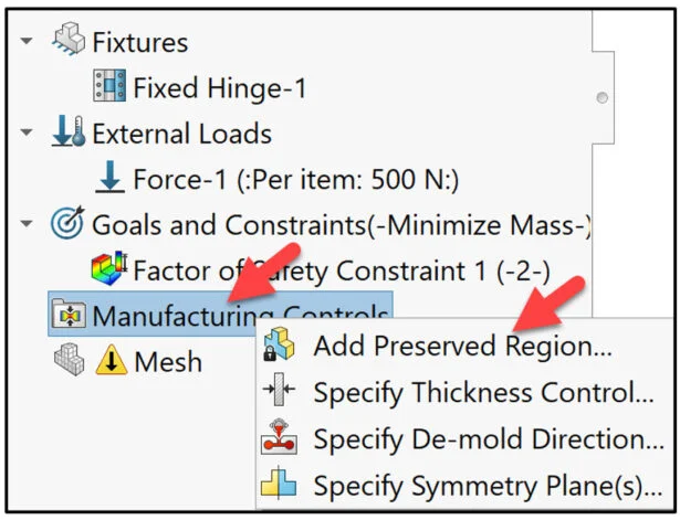
Manufacturing Controls provide the ability to control where and how material is removed. Most of the removed shapes are targeted for Additive Manufacturing, but you can tailor them for some of the traditional subtractive manufacturing processes (casting, milling, or stamping).
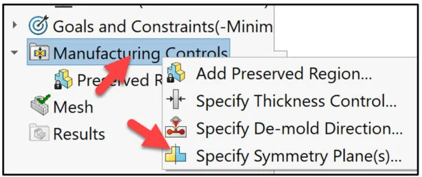
Right-click Manufacturing Controls in the study as illustrated.
Click Add Preserved Region.
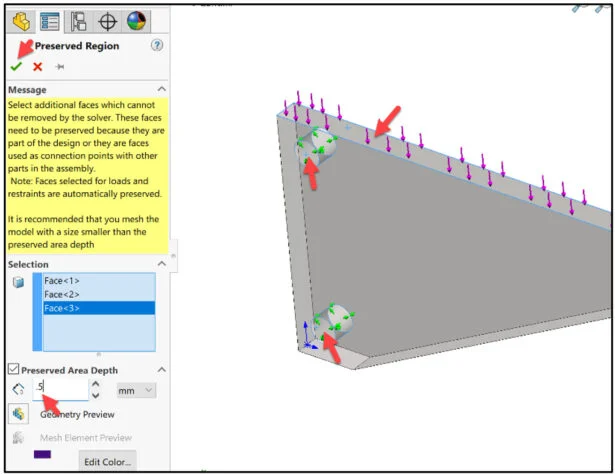
The Preserved Region PropertyManager is displayed.
Select faces which cannot be removed by the solver. These faces need to be preserved because they are part of the design. We cannot alter the mounting hole’s location and the Top face of the model for the applied force.
Select the three faces as illustrated.
Enter .5mm for Preserved Area Depth. This constraint forces the topology solver to leave these volumes unchanged in the final design, to ensure sufficient structural integrity in these locations.
Click OK from the Preserved Region PropertyManager.
Apply Symmetry to speed up the analysis and provide a uniform design. The model is Half Symmetry.
Right-click Manufacturing Controls. Click Specify Symmetry Plane(s) from the drop-down menu.
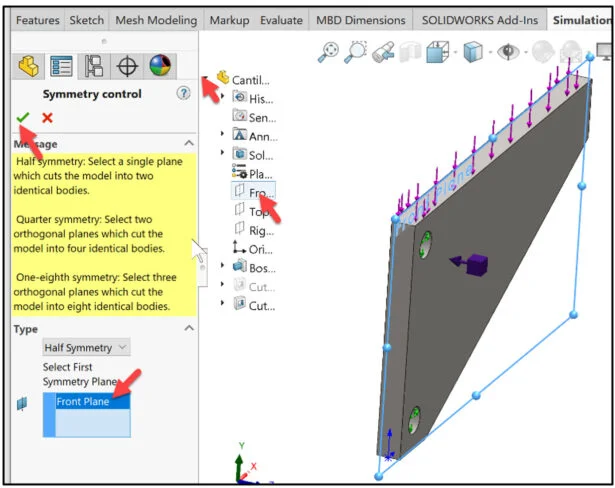
The Symmetry control PropertyManager is displayed.
The model is Half Symmetry about the Front Plane.
Click Front Plane from the Pop-out FeatureManager.
Click OK from the Symmetry control PropertyManager.
Address Mesh Control. This is your first iteration.
Right-click Mesh.
Click Apply Mesh Control.
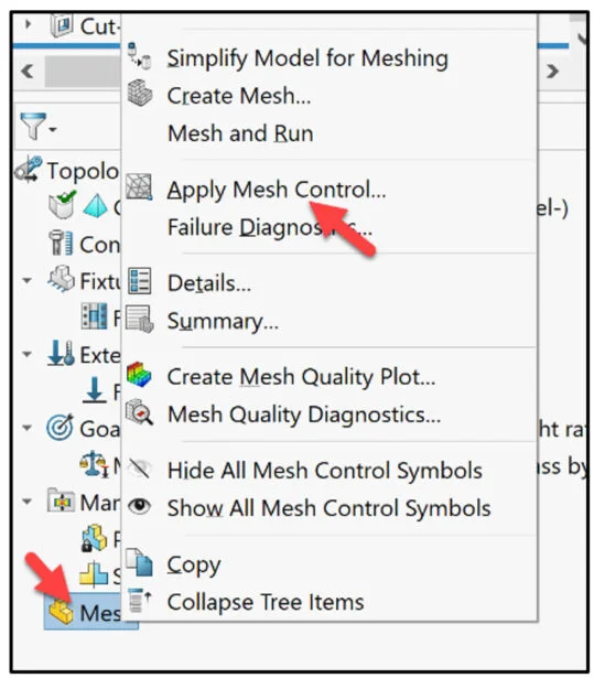
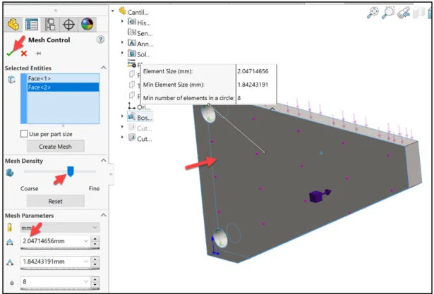
The Mesh Control PropertyManager is displayed. Mesh Control refers to specifying different element sizes at different regions in the model. A smaller element size in a region improves the accuracy of results in that region and provides a more organic shape, but takes a longer time to run.
Click the front face and back face of the Bracket in the Graphics area. Slide the slider to select an Element Size of approximately 2.05. Due to the selected mesh element size, run time is approximately 6 minutes. Note: If I lower the mesh element size to .952mm, run time is approximately 8 hours. In an Additive Manufacturing process, we can address this with the 3D Printer type, (FDM, SLA or SLS), material type, setup, and a lab experiment.
Click OK from the Mesh Control PropertyManager.
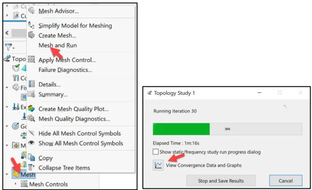
Right-click Mesh.
Click Mesh and Run.
The Topology Study 1 dialog box is displayed.
The View Convergence Data and Graphs icon displays real time the Convergence Data on Goals and Constraints. Due to the size of the selected mesh element for the first design iteration, the run time is approximately 6 minutes.
During a Topology Optimization, the program starts with the given maximum physical space of a component, which includes all elements, and through an iterative process determines a new material distribution that leads to a lighter, yet stiff shape.
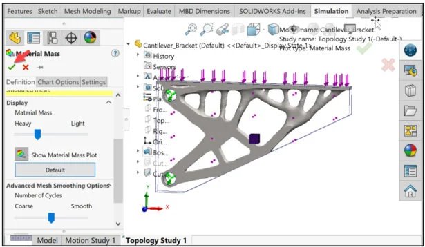
When the first iterative optimization process completes, view the optimized shape of the component in the Material Mass1 Plot.
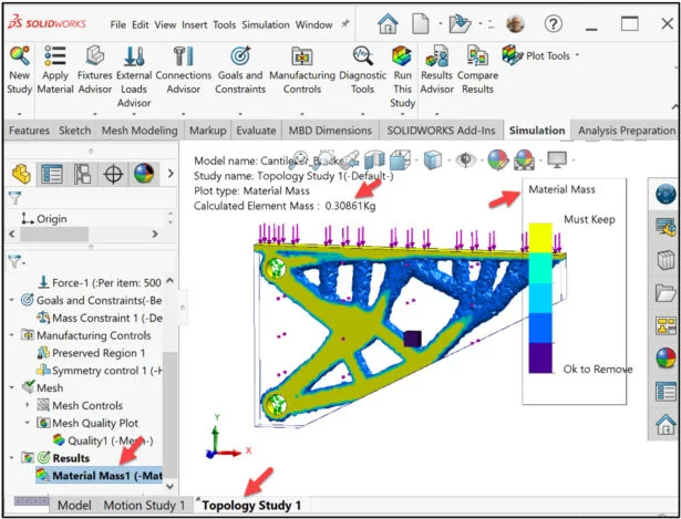
Right-click the Material Mass1 folder.
Click Edit Definition.
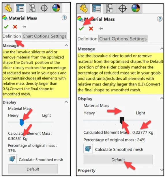
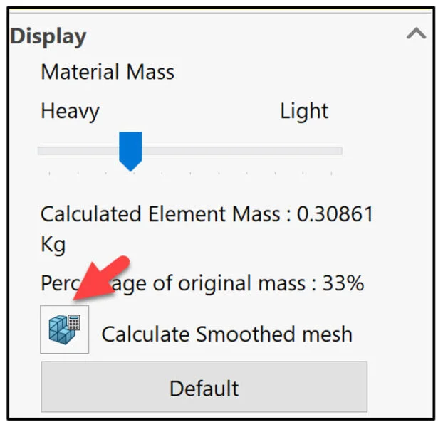
View the provided information. The Default position of the isovalue slider in the Display area removes those elements with relative mass density values less than 0.3.
The Material Mass PropertyManager is displayed. The original mass was 910.51 g with a FOS of 36.45. The new mass is 308.61 g with a FOS of 21.89.
Slide the isovalue slider to the left as illustrated. This will subtract mass from the existing model. View the results in the Graphics area. Note: You can later Edit this PropertyManager and address less material for the results.
In this example, return to the Default setting. Click the Default button.
Create a smoother surface mesh from the active Material Mass1 Plot.
Click the Calculate Smoothed mesh icon. This removes or modifies elements that create jagged edges and sharp angles.
View the results.
Click OK from the Material Mass PropertyManager.
Export Smoothed Mesh
What can we do with this shape? There are a few extraction techniques that you can apply.
Right-click the Material Mass1 folder.
Click Export Smoothed Mesh.
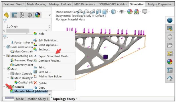
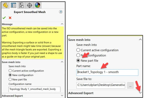
The Export Smoothed Mesh PropertyManager is displayed. View the default options.
We can export the mesh body as a separate configuration or open it as a new part file.
We will open the mesh body in a new part file.
Click New part file for the Save mesh into dialog box.
Enter Part name: Bracket1_Topology 1 – smooth.
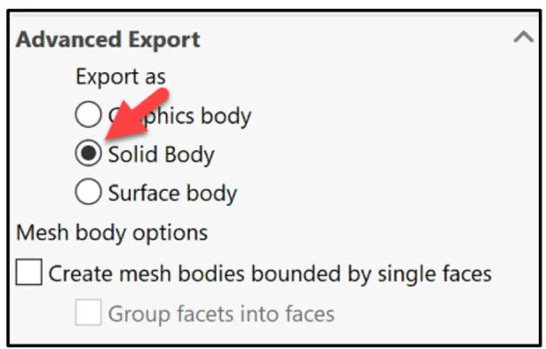
Select the down-arrow to expand the Advanced Export options.
View the default options. The Graphics body options export the smoothed mesh data in a lightweight, boundary geometry representation format. Select this option to import the Graphics Body document into your original part or assembly document, so that you can use it as a blueprint to help you modify the geometry of the original component.
The Solid Body exports the smoothed mesh data as a solid body (*.sldprt file format). Select this option for 3D printing operations. This option takes longer computational time to complete.
The Surface body exports only the surface geometry of the smoothed mesh data ( *.STL file format).
Select Solid Body.
Click OK from the Export Smoothed Mesh PropertyManager.
Open the Exported Solid Body in SOLIDWORKS.
Click the Model tab as illustrated.
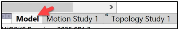
The SOLIDWORKS Graphics area is displayed. Display SOLIDWORKS Simulation results in the SOLIDWORKS Graphic area. This way, you do not have to switch between the simulation results and the modeling environment.
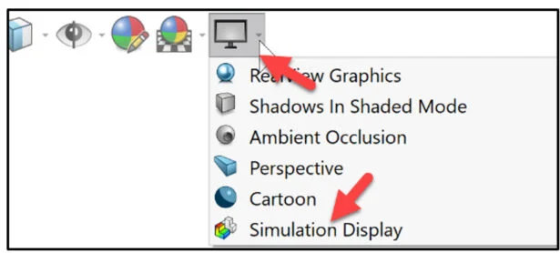
Click the drop-down arrow from the Heads-up toolbar.
Click Simulation Display.
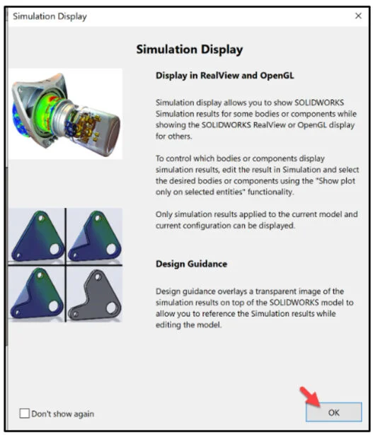
The Simulation Display dialog box is displayed.
Click OK.
The Simulation Display PropertyManager is displayed. View the options.
Check the Material Mass1 (-Material Mass-) box. Click OK from the Simulation Display PropertyManager.
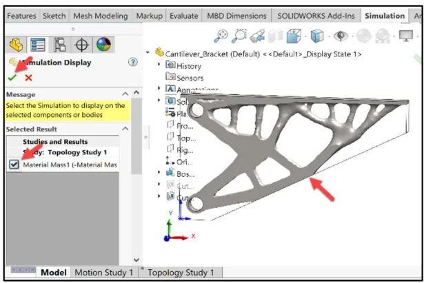
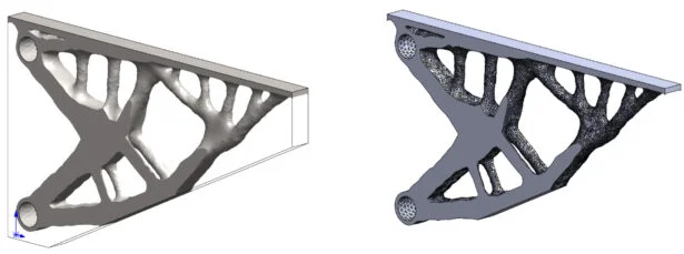
View the results.
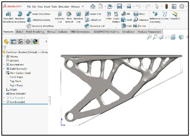
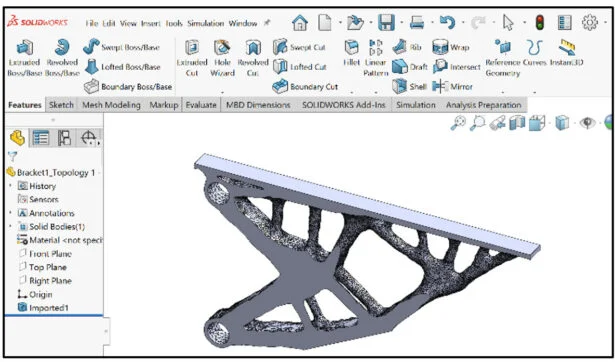
Open the Bracket1_Topology 1 – smooth mesh model from your Save in Folder.
View the results of the mesh model.
The lesson is finished for the initial Topology Study. Now you need to translate performance requirements to material requirements and the Additive manufacturing process. The answer is not in the back of a book.
In Lesson 4, we will explore a few Mesh Modeling tools in SOLIDWORKS using the Bracket1_Topology1-Smooth mesh model from Lesson 3.
Become a SWUGN Member
SOLIDWORKS and SOLIDWORKS Simulation Educators, register to be part of the SOLIDWORKS User Group Network (SWUGN) with virtual and in person meetings for ever thing about SOLIDWORKS and more.
Additional Resources for Educators and Students – MySolidWorks
You can find additional lessons and learning paths about SOLIDWORKS and SOLIDWORKS Simulation at My.SOLIDWORKS.com.
Design well, Marie