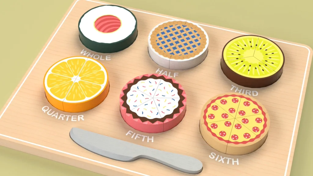

For this tutorial, I designed a 21-piece educational wooden fractions puzzle which includes a knife. Through exploratory play, children will recognize that fractions are equal parts that make up a whole, they can learn about fractions in a way that can be fun and easier to understand using food visuals. Under each segment, the puzzle base is labeled with the fraction they represent to further deepen a child’s understanding. In the tutorial, I demonstrate the whole design of the puzzle from start to finish, including how I modeled the whole puzzle as a multibody part, used save bodies to create an assembly, and used circular component pattern to place all the puzzle pieces. I also include some decal applications. If you would like to follow the tutorial, I have a file with the knife DXF and the decals used, available to download here.
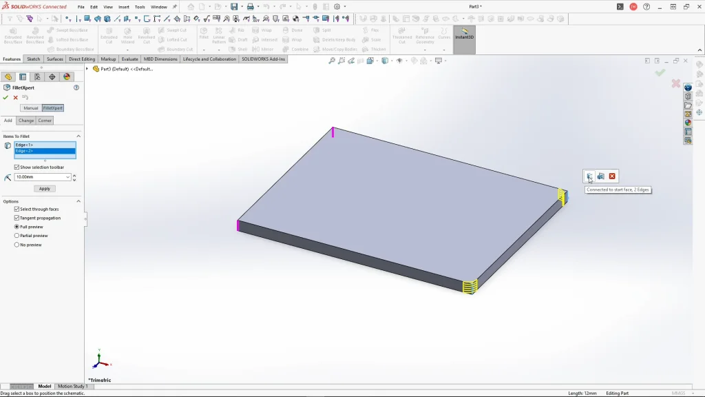
To begin, I started my sketch on the top plane and used the center rectangle. I sketched the base panel rectangle and extruded it by 12mm. Using the fillet feature, I’m filleting the corners of the base by 10mm, selecting one of the edges, the edge selection toolbar becomes visible (if this isn’t visible, check the show selection toolbar box under the items to fillet box) with this tool you can auto select edges quickly, the purple preview line shows you what edges would become filleted. I filleted the corners of the base as a separate feature rather than within the sketch as this is always easier to edit or remove.
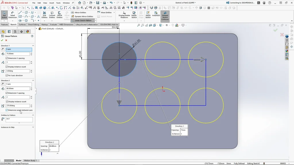
The next step was to create the cut outs for the puzzle pieces, for this I sketched a circle, and with linear sketch pattern I changed the instances to 3, and the spacing to 75mm. I could also add another direction to the pattern using direction two and inputting 2 instances. For the direction to move downwards, you’re able to move the arrow by dragging it which changes the direction angle and also the spacing, or you can type in the angle and spacing in the boxes to create a linear row below. If you don’t have all of the dimension and axes boxes checked, the pattern will not be fully defined, so just ensure these are all checked. You don’t need to have the display instance count checked to fully define the sketch.
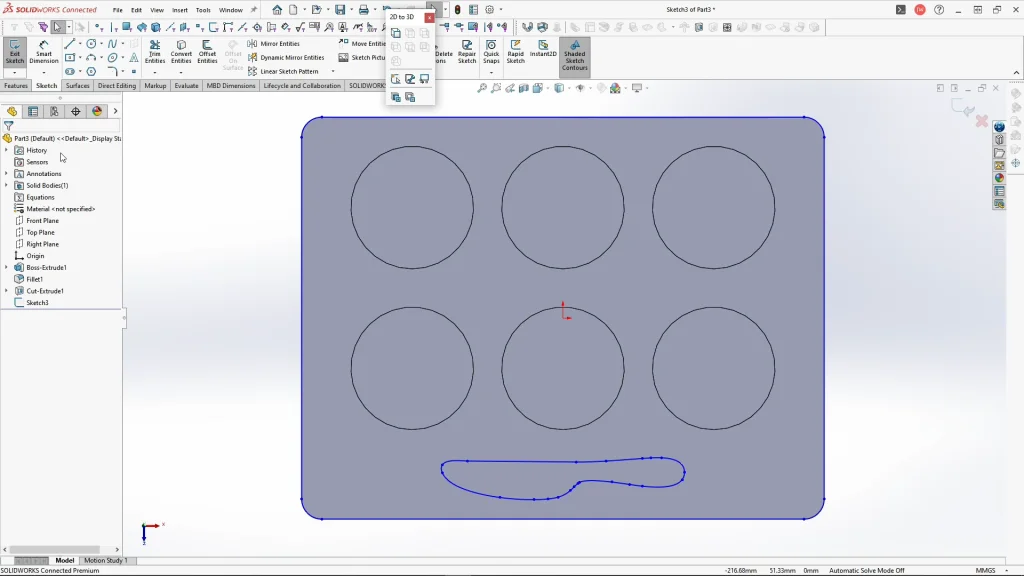
For the knife, I used a DXF sketch that I created in a vector software. Selecting the top face of the base panel, Insert, and DXF, I could browse and open the knife DXF file. In the import options, I unchecked the import as reference box and finish to bring the file in as a sketch. I created the sketch in mm, so it should import the same units. Just as a side note, the DXF I created in my vector software was sketched center to the document, so that when I exported it, and imported it into SOLIDWORKS, it would be center to my part. This is something I keep in model when I model in SOLIDWORKS. The circles were extrude cut by 3mm and the knife by 2mm.
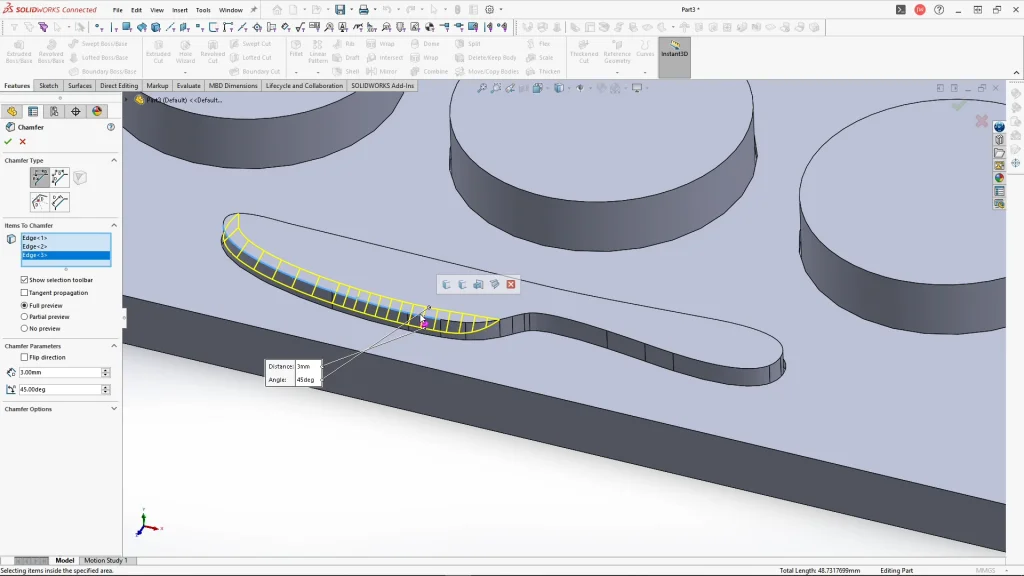
For the puzzle pieces, I sketched onto the face of the cut extrude and used offset entities to offset inwards by 0.5mm. I repeat the process for each circular face, they need to be created one at a time. Once all six sketches are created, I could extrude by 15mm unmerged, all the bodies need to be kept separate to use save bodies later on. I repeat the process for the knife on the face of the knives cut face. This was extruded by 6mm unmerged again. Using chamfer, I changed the chamfer dimension to 3mm, selecting the edge of the knife the whole top edge would fillet, however, to select certain edges, I needed to uncheck tangent propagation to see the preview below. This allows me to create the knives cut edge.
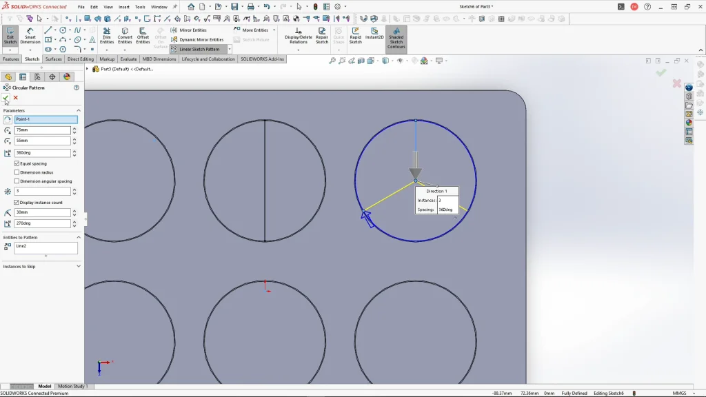
To create the puzzle fraction pieces, I began a sketch onto the top face of the extrusion. The first part remains a whole circle, while the second piece I sketched a straight line through the middle, which would create two parts. For the thirds piece, I used a line from the top edge to the center, ensuring I sketched from the edge of the puzzle piece and not the cut extrude edge of the base. It’s best to try and use the quadrant points of the circular edge to help fully define the sketch. With my line selected, I used the circular sketch pattern feature. For the parameters, I moved the center or axis for the pattern direction to the center of the puzzle piece, I then changed the instances to 3. The default circular pattern feature will pattern within 360 degrees and have equal spacing checked. This divides my shape into thirds. For the quarters piece, I sketched a vertical line from quadrant to quadrant, and another horizontally like this, dividing my shape into quarters. I repeated the circular pattern process to create the sketch for the fifths and sixths pieces.
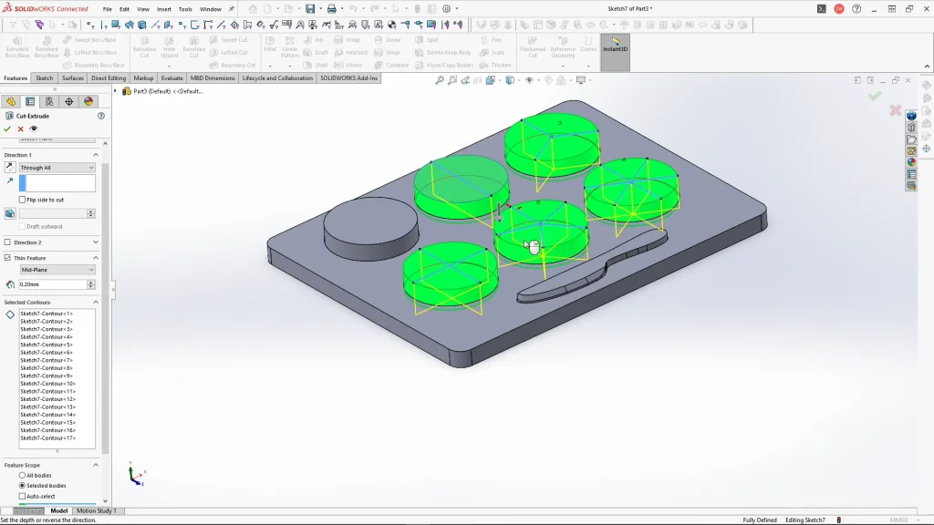
To divide the bodies into fractions, I used cut extrude with a thin feature, under direction one, I selected through all. For the thin feature, I cut midplane by 0.2mm. For selected contours, you need to select all of the sketched lines and change the feature scope to only cut through the puzzle pieces like below. When I apply it, the Bodies to Keep box will appear. Here, all bodies should be checked.
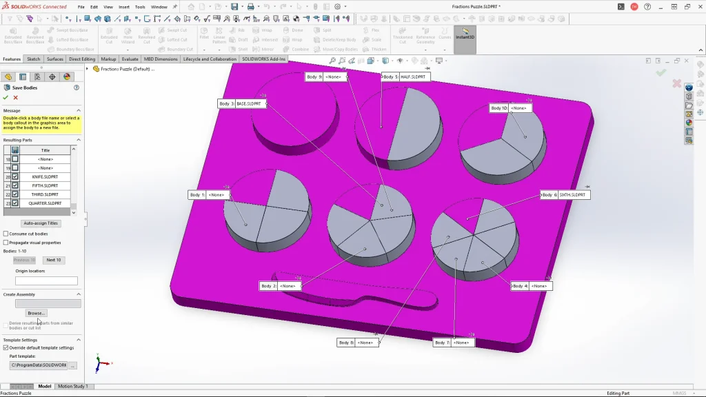
Before I use save bodies to create the puzzle assembly, I rename the puzzle bodies. Double clicking the body names, I rename each part, but I only rename one of each of the fractioned puzzle piece parts, as I could just repeat parts within the assembly. You need to save your part before using save bodies. From here, I can right-click solid bodies in the feature tree and select save bodies. For the resulting parts list, I selected the base, the whole part, 1 half piece, 1 third piece, a quarter piece, a fifth and a sixth, and also the knife part as seen below. I kept consume cut bodies and propagate visual properties unchecked, these aren’t necessary, but to create an assembly with the selected parts, I used browse, under create assembly, and named the assembly, and clicked save. This will then save all of the bodies selected as separate part files while also creating an assembly of those parts.
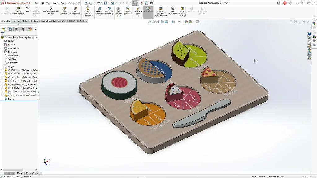
With my newly created assembly opened, I start adding decals. You don’t have to add these if you don’t want to, you can skip along to the assembly part, however I thought I’d include this within the assembly to demonstrate my whole design process.
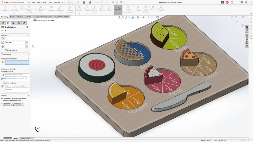
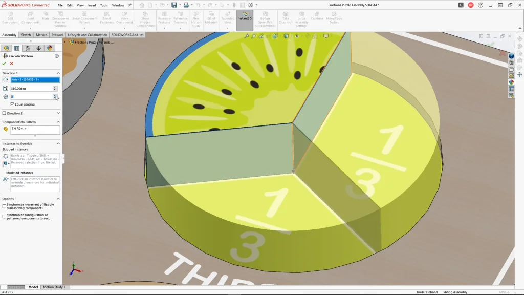
To quickly add the other puzzle pieces without having to worry about adding mates, I used circular component pattern. For the patterns axis I used view temporary axis, you could also use the inner circular face or edge of the base to create the pattern. It’s important to use the axis for the pattern rather than the edge of the piece, otherwise the pieces will be touching and they will pattern off center within the puzzle base. So, selecting this axis for the third’s piece, and the thirds part for the component to pattern, I changed the number of instance to 3, and applied it. You’ll see in the tutorial, that the component patterns with all of the appearances and decals attached, and it is in the correct position without any mates applied.
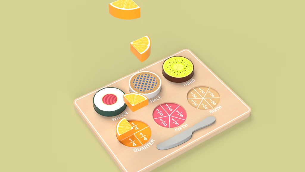
I repeated this feature for the other puzzle parts ensuring each instances matched the fraction number. With my puzzle complete, I used an exploded view to create a rendered animation within SOLIDWORKS Visualize, you can see the result within the tutorial.