
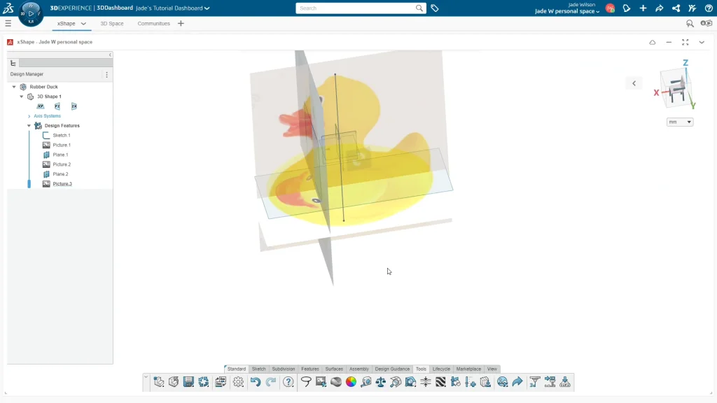
Such a simple little bath toy found in most people’s bathrooms, but modeling this in SOLIDWORKS would be a challenge, it has so many curves and organic shapes, especially looking at the ducks bill. So, I decided to move onto the 3DExperience Platform, and use the 3d Sculptor roles xShape app. Before I began any modeling I used some images taken from the internet of a side, front and top view of a generic rubber duck to use as picture guides.
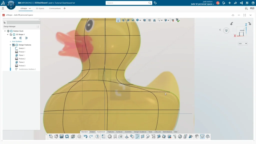
Starting a new component, I began my model by sketching a guideline of 100mm and placing it midpoint to my axis. This helps me to control the overall height of my rubber duck and gives me a guide in which to resize my rubber duck images. I added the side view of the duck onto the ZX plane and changed the image transparency to around 45, this makes it easier to see all of the subdivision shape as I’m modeling it. Using the advanced settings, I’m able to flip the image horizontally, and scale the image by percentage keeping it center to my axis. I scaled it down until the duck falls between the guide sketch line.
For the front image of the duck, I added a new plane off the YZ plane dragging it to line up with the start of the neck and bill, then I added the front view image of the duck. Selecting the XY plane, I’m adding another new plane to sit along the duck at the widest part of its body. Then with the new plane selected I could add the top view image of the duck.
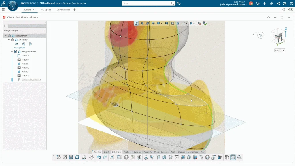
For the main duck body, I used the globe surface as the starting shape, and snapped it onto my guide sketch. I switched on the symmetry tool along the ZX plane, that way I could edit the shape on one side and the duck would remain symmetric. A green line shows me that the symmetry feature is active and along which line it is mirroring. Before I began modeling, I altered the transparency of the shape to see the guide image underneath.
When I got to the tail of the duck, I needed to extrude some of the shapes faces to form the tail. The view from the top of the duck is very square. Again, I only needed to move points from one side of the duck to reshape the profile. The tail needed more loops to taper it more and make it easier to shape.
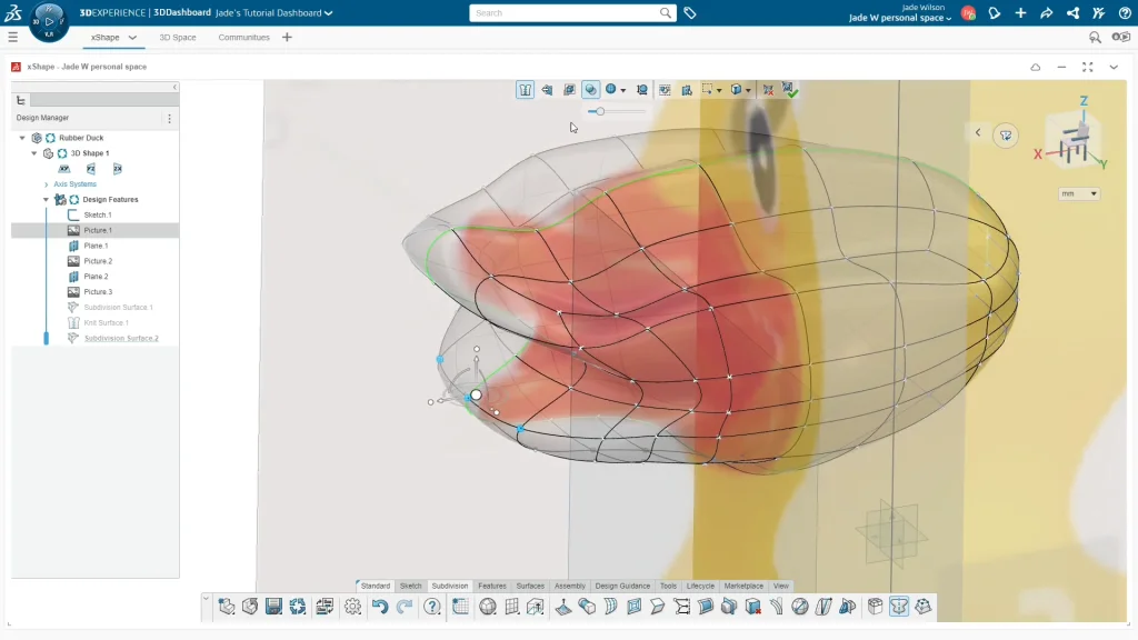
To create the bill of the duck, I used the quad ball. You may wonder why I select specific shapes, this comes from experience modeling certain shapes, I have learned what shapes work best for creating certain forms. The bill was a little more finicky of a shape to model, but like the duck’s body I began with the side view and inserted more loops where I needed. From the top view, I shaped the bill in reference to the photo, but not too closely that I would change the bill from other views; again the images are just guides.
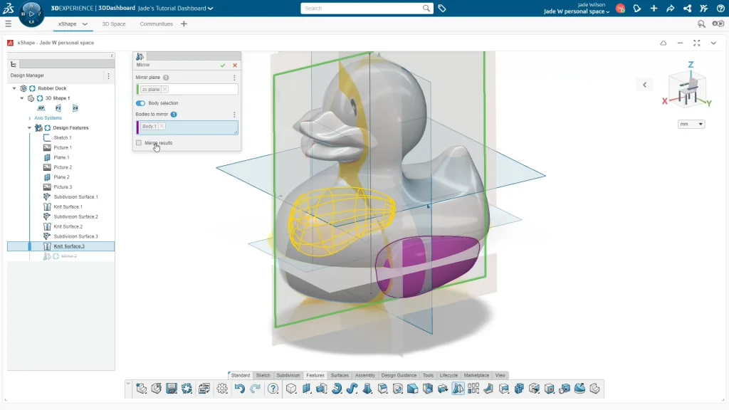
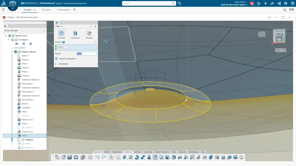
A wing was modeled using the cone subdivision surface, I shaped the wing around the duck’s body, and pushed it into the duck, the wing shape can be fairly simple in its design. Once done, I used the mirror feature. With the wing body selected, I kept merge result unchecked as I wanted the duck’s bill to remain separate, this makes it easier to color the parts later on. Instead, I combined the wing bodies with the duck using the combine feature. This allows me to add a small 5mm fillet around the edge of the wing creating a more molded appearance to the rubber duck.
The next feature of the duck was the squeaker hole. For this element I revolve cut a dome out of the base and cut a small hole into the duck by 2mm from the geometry. This hole allowed me to select its inner faces and shell the duck body by 1mm. To finalize this feature of the duck, I revolved a lip profile around the opening of the hole which some molded rubber ducks have.
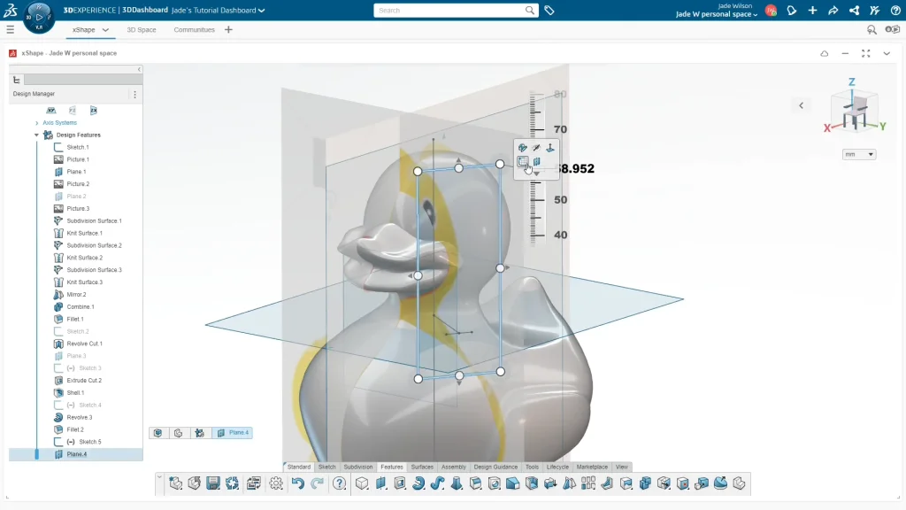
Sketching onto the XY plane, and viewing from the top, I sketched a perpendicular line midpoint to the end of my line, to sit facing the ducks head where I want the eye to project from to split the ducks face. I added a new plane selecting the line and the midpoint of the perpendicular line as the reference so that the plane sat along my sketched guide.
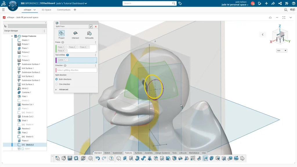
From here, I sketched an ellipse near and in line with the eye from the image. Sketching the eye directly on top of the guide image would sit wrong, so I sketched to the right of the eye on a slight angle. Then using features and split face, I could select all of the faces of the duck that the sketch needs to project onto. Once applied, I can see when I hover over the ducks face that the face has split to form the outline of the ducks eye. I repeated this process for the pupil of the duck and mirrored the eye over.
With the duck fully modeled, I applied appearances to the ducks body, bill and eyes, this makes it easier to preselect parts in SOLIDWORKS Visualize and edit the individual appearances and colors. I saved my rubber duck and opened it up in SOLIDWORKS Visualize to render, you can see an animation of the ducks falling at the end of the tutorial.