

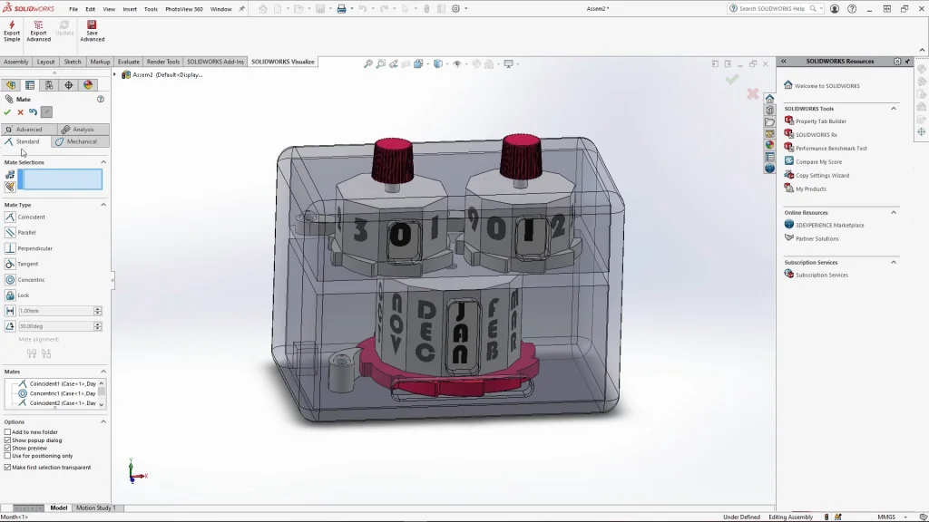
To celebrate the New Year I wanted to create a 3d perpetual calendar to make a countdown animation. Before starting this tutorial, download the parts here. The calendar is made up of a case that hold the two induvial day dials, the months dial and 3 ratchet pawl attachments. The dials all have ratchet wheels attached to them making the assembly simpler. The 3 dials for showing the days and the month of the calendar are mated concentric onto circular faces of the case making it easy for them to rotate. The pawl parts which work with the ratchet mechanism of each dial are also mated onto pins within the case. The pawls are also mated coincident to a tooth of the ratchet to hold each dial in place ready for the motion study. These mates are suppressed before starting the analysis otherwise it would not be able to move. With parts being mated within the calendar case, I turned on the transparency of the part to make it easier to see inside, I also used ‘select other’ to select inner faces of the case.
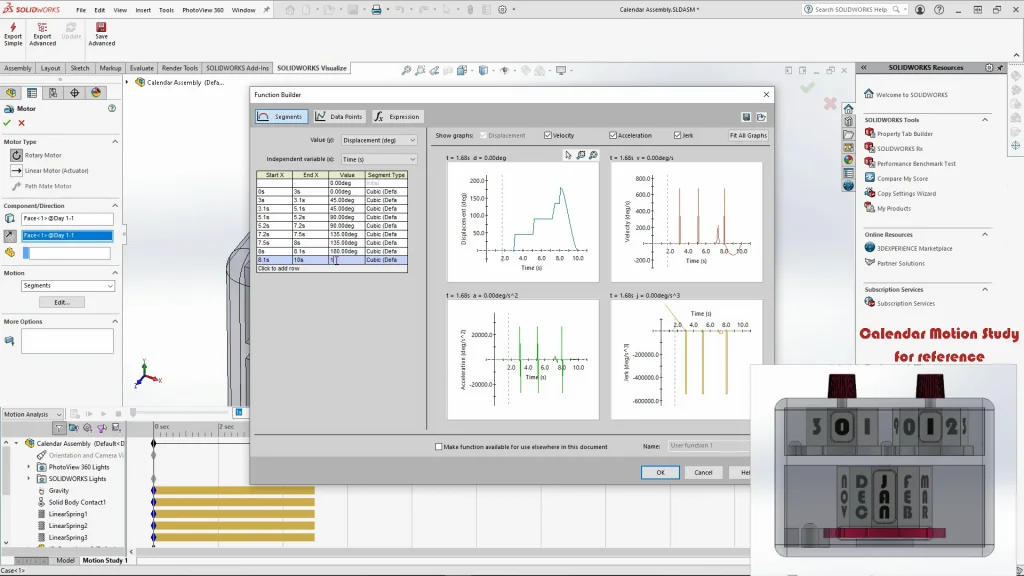
Once everything is mated into place, I could start a Motion study, for this I chose to create a motion analysis using gravity, contacts, motors, and linear springs. The most important aspect of the study is the motor with motion segments. The motors are applied to the dials where the user of the calendar would turn them. All motor directions needed to be reversed to go clockwise in the direction of the ratchet so that the days and months run in order. Under motion settings of the motor, selecting the dropdown menu you can select segments. Here I can input the timings for when the motors will turn within the study, by what degree they turn and for how long. I have pre-calculated all of these settings through trial and error to fine tune them. During the tutorial, I explain the timings and rotation degrees using the finished motion study animation. You can see looking at the displacement graph in the function builder, the steps of how long the motor is turning, when it is at a standstill and by what degree it has rotated is illustrated.
This motor type was especially useful for this tutorial as I could make each dial move to specific days and months at the timings, I wanted them at. This would be impossible to time using motors without segments as I could make the day dials line up with each other, and pause when they hit December 10th, 20th, 31st then the January 1st, the months dial turns. Each dial had to be turned based on the number of sides they have this determined the degree I would input for the displacement value. The first number for the days dial, has 8 sides (rotates 45 degrees per side), the second days dial has 10 sides (rotates 36 degrees per side) and the months dial has 12 (rotates 30 degrees per side). The value degree on each segment of a motor, is simply the total degree of rotation since the starting position at 0 degrees. So, when inputting the degrees for turning the dials, you need to times the degree by how many face turns I need to do. You can input the same degree as a previous segment to hold the motor in place.
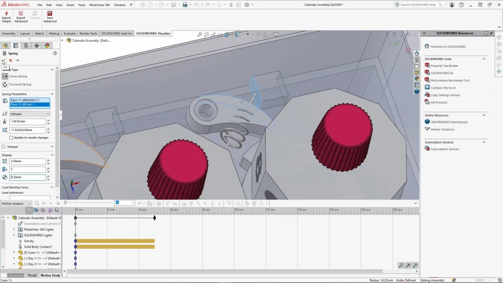
For the dials to work, I created ratchet mechanisms, but for these to move in the motion analysis I needed to add springs behind the pawl parts, this is what the blocks are for inside the case. These act as a parameter for the spring to attach to. You will see a preview of the spring as seen below, but it will not stay visible once applied.
With the finished motion analysis, I exported it from SOLIDWORKS directly into Visualize to render the animation. You will find this at the end of the tutorial.