

Hello to all,
Welcome to the new edition of the SOLIDWORKS® Support Monthly News! This monthly news blog is co-authored by members of the SOLIDWORKS® Technical Support teams worldwide. Here is the list of topics covered in this month’s Blog :
- PDM Professional User and Groups Management for Windows Login
- Best Practice for IF Functions in Equations
- Why SHELL mesh calculates unexpected results?
- Easy way to determine the source location of SOLIDWORKS® installation files
- Working with SOLIDWORKS® Visualize Shadow Catcher
PDM Professional User and Groups Management for Windows Login
By Gordon PURSEL
This blog is for PDM Professional administrators interested in using Windows Login and importing groups from Active Directory (AD). If you are new to PDM Windows Login, I also recommend reviewing the SOLIDWORKS® PDM Administration Guide > Importing Active Directory Users into Groups (For SOLIDWORKS® PDM Professional only) and Knowledge Base Solution S-077650 for more details.
To begin, if you are still trying to determine if Windows Login is best for your organization. Below are few time saving benefits to using Windows Login and Importing Groups from Active Directory.
- The PDM ‘Add Users’ and ‘Importing Groups from Active Directory’ wizards automatically creates Users with PDM User Properties mapped to AD attributes such as login name, full name, email, etc. Automatically creating users and repurposing the AD attributes is a real time saver when creating a large number of users.
- The PDM ‘Add Users’ and ‘Importing Groups from Active Directory’ wizards can optionally assign users to groups imported from Active Directory.
- Passwords and policies are managed by Windows Active Directory.
- User properties and group membership changed in AD can be updated in PDM via ‘Update from Active Directory…’. This includes adding new users to PDM, adding users to imported groups, removing users from the imported group, and updating user properties.
To configure SOLIDWORKS® PDM Archive Server for Windows Login :
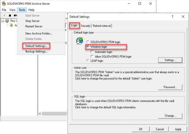
- To use Windows Login, the SOLIDWORKS® PDM Archive Server login type must be set to Windows login. If the Archive Server is not replicated, the setting can be configured in the Default Settings > Login tab. Note: When users login into PDM they are prompted for their Windows authentication credentials. Using the sub-option ‘Automatic login’ logs in Windows users automatically without prompting for credentials.
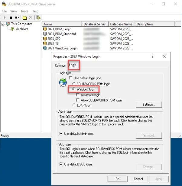
- The setting can also be configured in the vault specific Properties > Login tab.Tip: Consideration to set Windows Login in the Default Settings or vault specific settings depends if all vaults default to use the same Windows Login > Settings and allow creating the same users. For example, if you plan to have multiple vaults containing different Windows users, be sure to configure Windows Login at the vault specific properties.
- On the Login tab > Windows Login > Settings add a group containing users who log into PDM
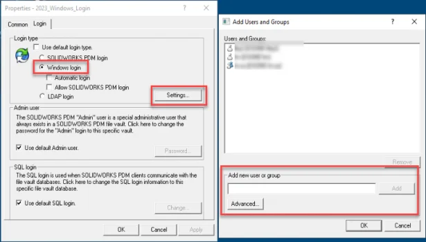
Tip: Configuring the Windows Login > Settings is where we see common mistakes. Following these guidelines will improve active directory lookups during PDM login and synchronizing PDM user and groups imported from active directory and avoid PDM access to unintended users.
- Create a Domain group containing ‘only’ PDM users then add that group. This is preferred even when planning to import AD groups.
- Do not add default ‘Doman Users’ group.
- Remove the Local Built-In users and groups
Creating Windows Users in SOLIDWORKS® PDM Administration Tool
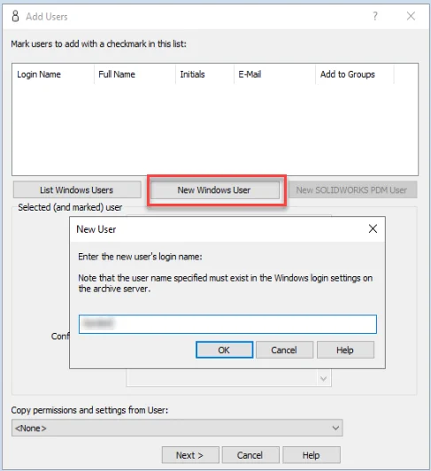
- The PDM Admin can import Windows Users from the ‘Users’ or ‘Groups’ node. This first example shows the ‘Add Users’ dialog from the ‘Users’ node.
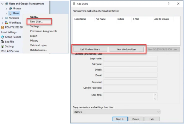
- The ‘New Windows User’ can be used to list specified users from the Archive Server Tool > Windows Login > Settings.
- ‘List Windows Users’ presents a list of users from the Archive Server Tool > Windows Login > Settings which are not already in the PDM vault. The ‘Add to Groups’ checkbox will add users to their appropriate imported AD groups.
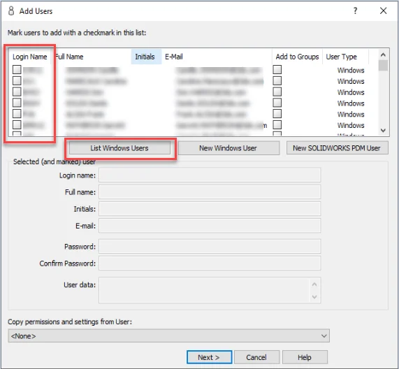
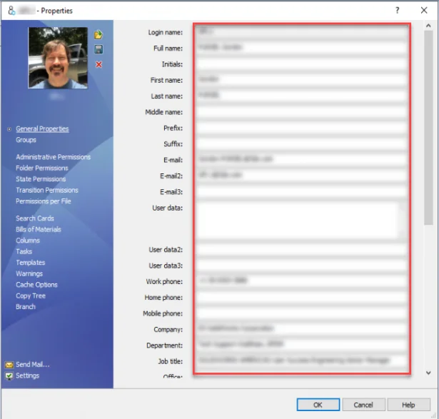
- The users created from either step will import User Properties from AD.
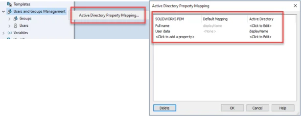
Tip: Use ‘Active Directory Property Mapping’ to override default user property mappings or map properties such as ‘User data’ that are not mapped to any Active Directory attribute
Importing Windows Groups from Active Directory
- To import AD Groups use ‘Import from Active Directory…’ from the Groups node.
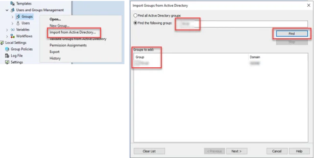
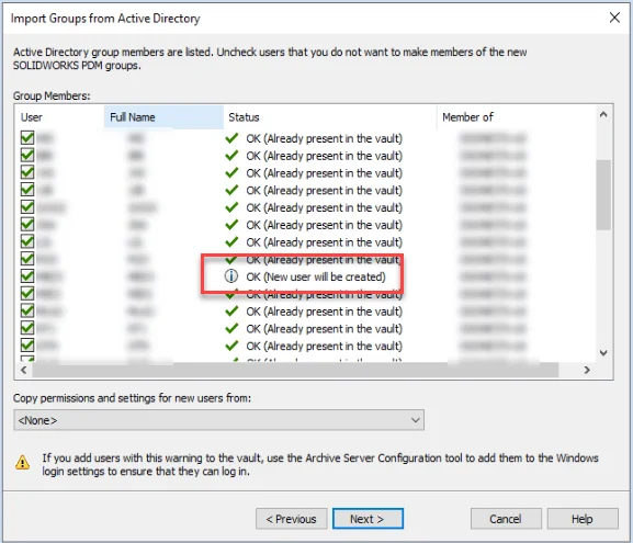
- The next dialog presents a list of users from the AD Group. The Status column is used indicates if the user exists in PDM or if the new user will be created. Selecting the checkbox in the ‘User’ column either creates new users or adds existing users to the group.
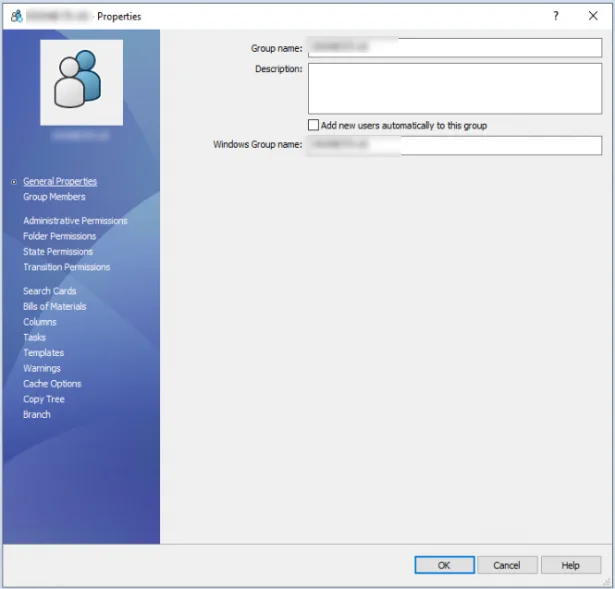
- At the end of the wizard, set the group permissions for the PDM vault
Best Practice for IF Functions in SOLIDWORKS® Equations
By Mahendra SAVITA
When you use the IF function and assign a specific decimal value to the Global Variable or the value to compare with, you may get an unexpected result because of the floating-point math done by equations.
SOLIDWORKS® uses floating-point math to compare values. For example, if you specify a Global Variable of 2.2, SOLIDWORKS might evaluate it as 2.2000001 or 2.1999998. In such cases, the comparison returns 0 (False) instead of 1 (True).
To avoid this situation, use a tolerance value in your comparison equation. In this example, you create a tolerance of 0.0000001.
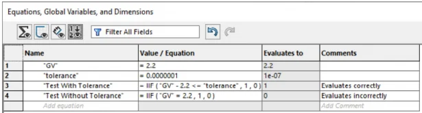
Under Value/Equations, create the IF statement as follows:
= IIF (“GV” – 2.2 <= “tolerance”, 1, 0)
In the comparison IF function, Test With Tolerance, the Global Variable GV minus itself is less than or equal to the tolerance, so the equation Evaluates to 1, the expected result.
Note that the Test without Tolerance unexpectedly Evaluates to 0.
Why SHELL mesh calculates unexpected results?
By Suresh NIKALAJE
SOLIDWORKS® Simulation Help description on the topic ‘Shell Definition PropertyManager’ summarizes: “The program does not offset load and boundary condition definitions applied on the selected surfaces. Apply all loads and boundary conditions at the selected surfaces where the shell mesh is created”
Hence, it is important to understand how exactly the load offset works in case of shell, and the applicable modeling technique to avoid generating unexpected results.
To exemplify the outcome, consider a 100 mm long a plain carbon steel plate with base dimensions 20 mm X 4 mm under 100N tensile load. A static study defined to conduct four separate and identical tests using different modeling approaches as shown in the following images –
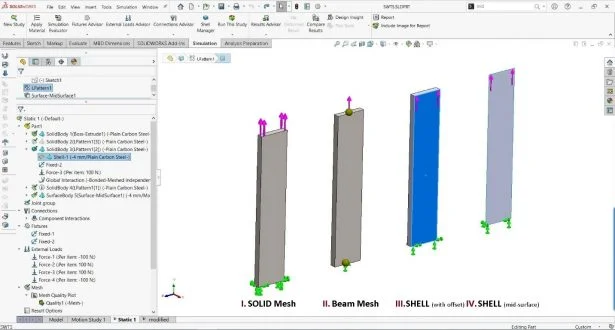
- The first body, treated as SOLID, fixed at bottom end and tensile load applied on top face
- The second body is treated as a BEAM, fixed at bottom joint and tensile load applied on top joint.
- The third body uses the ‘Define Shell by Selected Faces’ option. There is a ‘Top Surface’ offset, bottom edge fixed and tensile load applied on top edge.
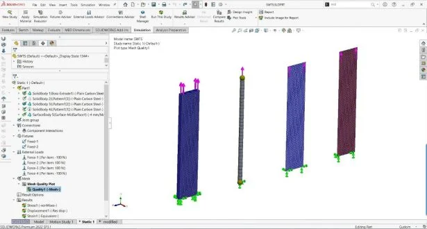
- The fourth body also uses the ‘Define Shell by Selected Faces’ option defined using middle surface, bottom edge fixed and tensile load applied on top edge, mesh model as shown in the following images.
After study is completed, post processing gives surprising displacement results. Here a tensile load (axial) in Y direction is the only dominant load; ideally, it would results only stretching of the plat. Therefore anticipated UX: X Displacement is 0 micron however in case of example III. SHELL (with offset) appears bending, and X Displacement detected is 0.044 micron, which is unexpected, as shown in the following images,
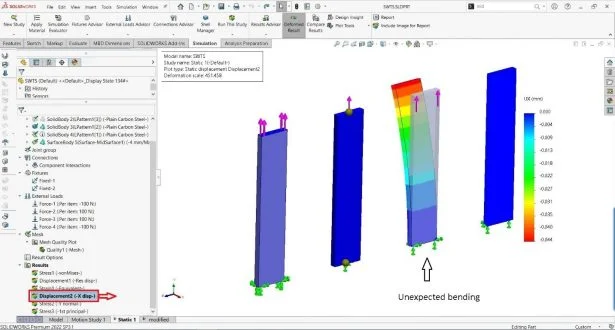
The third body uses the ‘Define Shell by Selected Faces’ option, with a ‘Top Surface’ offset, shows the bending effect, because:
- The software does not offset the force. The software applies the force at the exact location of the edge that selected for the force.
- The program offsets the midsurface with a distance equal to half the thickness of the shell
Thus, a tensile force / compressive defined on a flat shell does not cause any bending if you apply the load in the same plane as the midsurface of the shell (this is always the case when there is no shell offset).
Consequently, in this case, the load is not in the same plane as the midsurface of the shell. There is a half thickness offset of the force with respect to the midsurface of the shell. This creates a bending moment equal to the force value times half the thickness of the shell.
It is not possible to offset the force. In this case, the solution to avoid causing bending in the shell is to edit the shell and not use any offset, for additional information refer KB S-078933.
Easy way to determine the source location of SOLIDWORKS® installation files
By Deepika PUJARI
While diagnosing issues related to SOLIDWORKS® Installation, you may need to know the source file location. In such situation, browsing through many locations and folders may not be ideal. One of the practical and quick methods of finding the source file directory of a program is through the Control Panel menu. The Control Panel has more columns than it shows by default. Here is what you need to do:
- Open the Control Panel and go to Programs.
- Click ‘Uninstall a program’. This will take you to the list of installed apps.
- Right-click the title of any one of the columns and from the context menu, select ‘More’.
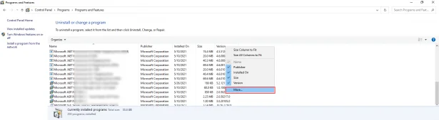
- ‘Choose Details’ dialog box will appear listing the various columns you can enable. One of them is ‘Source’ and if you enable it, you will be able to view the folder location the application is installed from.
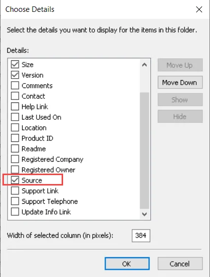
The ‘Source’ column will show you the location of Install files for most of the applications.
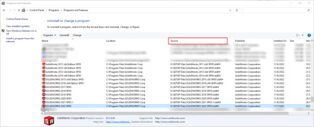
The information in this column is helpful when diagnosing SOLIDWORKS® installation errors like for example 1706, which is: ‘The Installation Manager cannot find required source files for product SOLIDWORKS® [version and service pack]’.
Working with SOLIDWORKS® Visualize Shadow Catcher
By Richie MORE
SOLIDWORKS® Visualize allows you to create stunning photo-realistic images and videos with the existing design CAD data.
To achieve a Realistic render, requires precisely placing the object shadows as per the preferred environment. We can have a control over the shadow placement with Shadow Catcher.
Procedure to work with Visualize Shadow catcher
Step 1– Open a Visualize Project. Add a background image as BackPlate. Match the CAD model to the BackPlate.
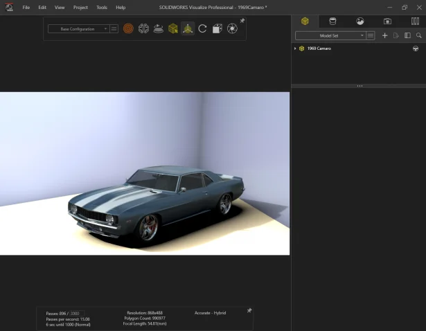
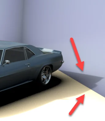
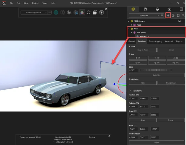
Step 2– Notice, the shadow does not correctly display near the walls. The shadow must fall on the wall, and not pass linearly as if the wall does not exist.
Step 3– From the Model tab > Add Wall primitive, and align it to the image wall.
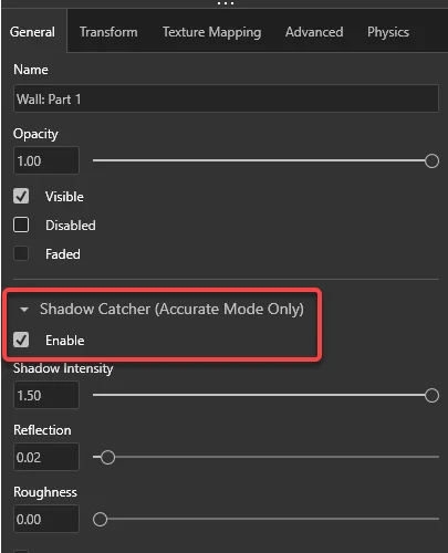
Step 4– Enable “ Shadow Catcher “.
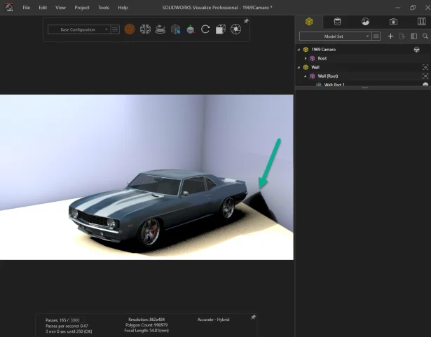
Step 5– Now the shadow is correctly places over the wall as in the BackPlate image.
Noteworthy Solutions from the SOLIDWORKS® Knowledge Base

When I right-click a part, drawing or assembly file, why does the SOLIDWORKS® file utility label not appear?This problem could happen after a Windows® or SOLIDWORKS® update. To get more information, see solution ID: S-079838

When I use the SOLIDWORKS® PDM quick search or integrated search functionality, why do the SOLIDWORKS file open or save dialog boxes stop responding (hangs or crashes)?This problem can happen on a SOLIDWORKS® PDM client workstation if the file type associations for SOLIDWORKS files are incorrect. To get more information, see solution ID: S-079778

What can I do if every SOLIDWORKS® Flow Simulation project I run shows a ‘Preparing model’ Solver Monitor status indefinitely and any FloXpress analysis never finishes the ‘Meshing in progress’ step?To get more information, see solution ID: S-079776